
Method for tracking and identifying bonding points on surfaces of casting blanks

A bonding point and slab technology, which is applied in the direction of casting equipment, indicating equipment/measurement equipment configuration, manufacturing tools, etc., can solve problems such as unqualified surface quality of slabs, scrapping, and poor identification of bonding points. , to achieve precise positioning and reduce data dependence

Active Publication Date: 2020-08-07
CONTINUOUS CASTING TECH ENG OF CHINA
View PDF7 Cites 0 Cited by
  • Summary
  • Abstract
  • Description
  • Claims
  • Application Information

AI Technical Summary

Problems solved by technology

[0005] In view of the above problems, the purpose of the present invention is to provide a method for tracking and identifying the bonding points on the surface of the slab, so as to solve the problem that the current breakout prediction method cannot identify the bonding points well, resulting in a large number of slabs due to the occurrence of bonding points. As a result, the surface quality of the slab is not up to standard and it is scrapped.

Method used


Image

  • Method for tracking and identifying bonding points on surfaces of casting blanks
  • Method for tracking and identifying bonding points on surfaces of casting blanks
  • Method for tracking and identifying bonding points on surfaces of casting blanks

Examples


Embodiment Construction

[0049] In the following description, for purposes of explanation, numerous specific details are set forth in order to provide a thorough understanding of one or more embodiments. It may be evident, however, that these embodiments may be practiced without these specific details.

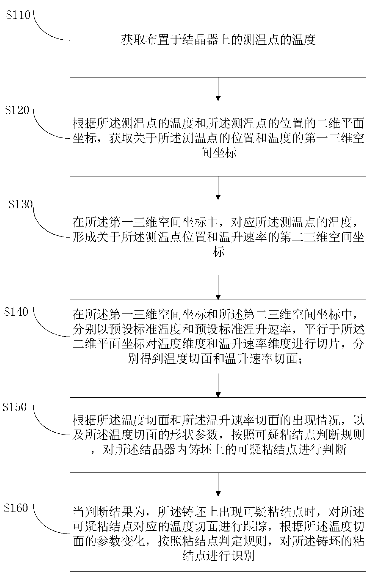
[0050] In view of the problems that the existing breakout prediction method proposed above cannot identify the cohesive points well, resulting in a large number of slabs being scrapped due to the occurrence of cohesive points, resulting in unqualified surface quality of the slabs, the present invention proposes A method for tracking and identifying bonding points on the surface of slabs has been developed. Using the method of the present invention, the identification of bonding points with "self-healing" ability can be realized. Online identification will affect the surface quality of slabs without the risk of breakout the bonding point.

[0051] Specific embodiments of the present invention will be ...


PUM


Abstract

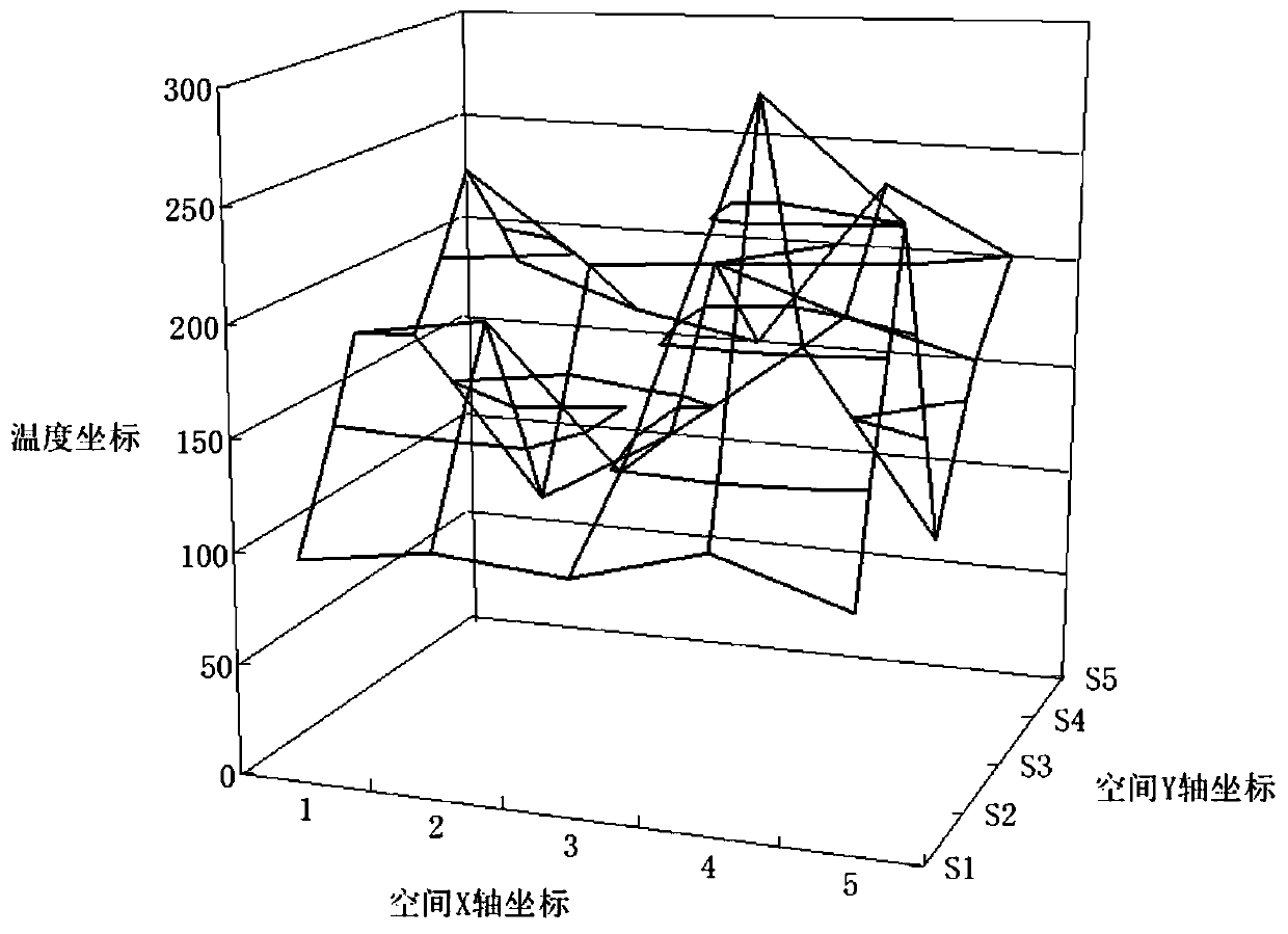
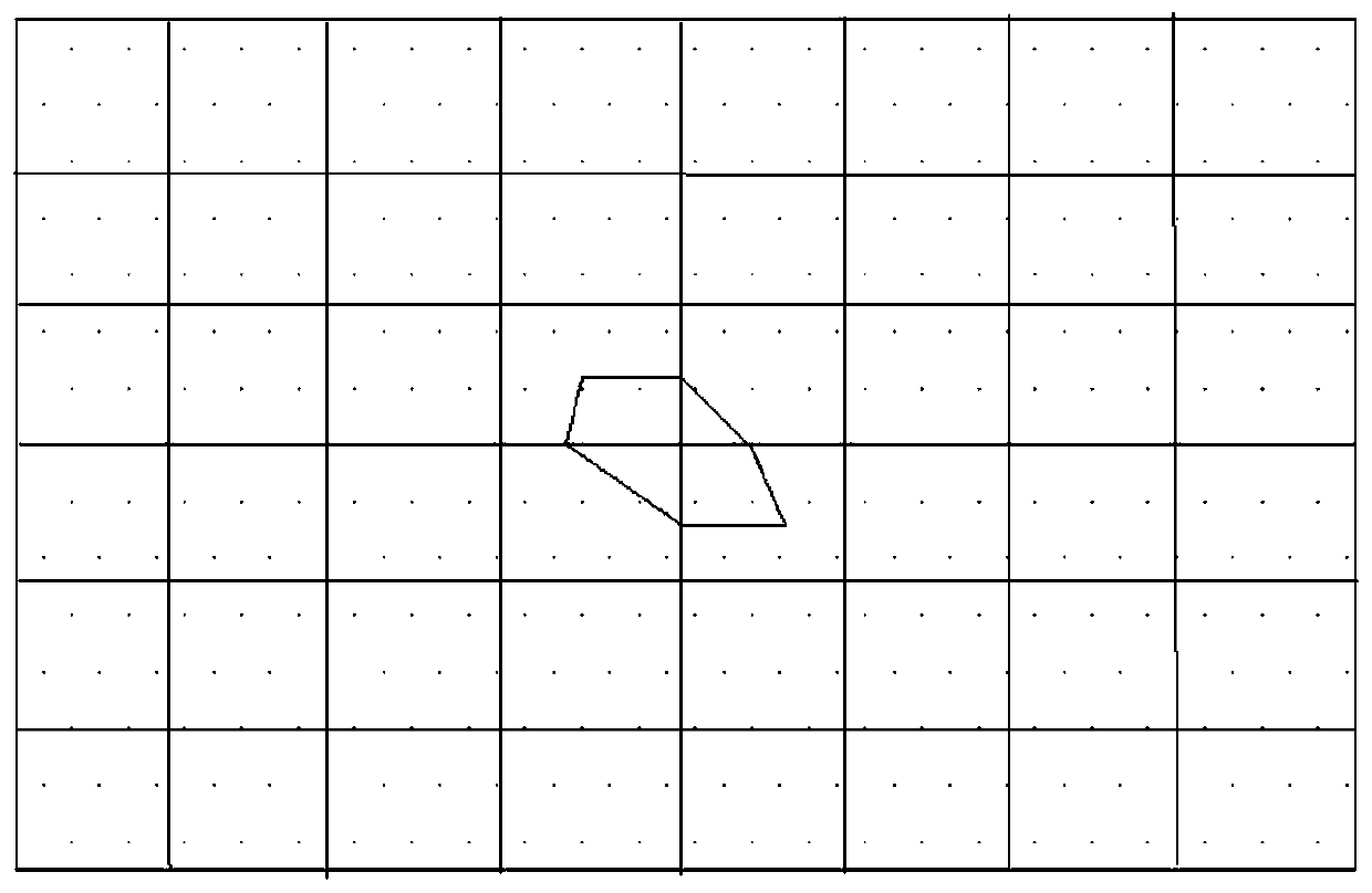
The invention provides a method for tracking and identifying bonding points on the surfaces of casting blanks. The method comprises the following steps of acquiring the temperatures of temperature measuring points arranged on a crystallizer; according to the temperatures of the temperature measuring points and the two-dimensional plane coordinates of the positions of the temperature measuring points, obtaining first three-dimensional space coordinates about the positions and the temperatures of the temperature measuring points; corresponding to the temperatures of the temperature measuring points, forming second three-dimensional space coordinates about the positions of the temperature measuring points and the temperature rise rate; obtaining a temperature tangent plane and a temperature rise rate tangent plane at a preset standard temperature and a preset standard temperature rise rate; judging the suspicious bonding points on the casting blanks in the crystallizer according to the temperature tangent plane and the temperature rise rate tangent plane; and tracking the temperature tangent plane corresponding to the suspicious bonding points, and identifying the bonding points of the casting blanks according to the parameter change of the temperature tangent plane. According to the method, the problem that the bonding points cannot be well identified through an existing breakoutforecasting method can be solved.

Description

technical field [0001] The invention relates to the technical field of continuous casting technology, and more specifically, relates to a method for tracking and identifying bonding points on the surface of a slab. Background technique [0002] Breakout accident is a very harmful production accident in continuous casting production, and more often it does not reach the level of breakout, but due to the occurrence of bonding points, there will be uneven surface quality problems on the surface of the billet. The surface quality is lighter than the surface quality brought by the speed reduction treatment after the breakout prediction, but it also affects the use of the billet. It must be removed by surface treatment, and even because of the appearance of a surface bond, the area where it is located The slab will be cut off. Once it is not found, the entire billet will be scrapped due to unqualified surface quality. [0003] The characteristic of this kind of bonding point is ...

Claims


Application Information

Patent Timeline
Patent Type & Authority Applications(China)
IPC IPC(8): B22D11/18B22D2/00
CPCB22D2/00B22D11/18
Inventor 钱亮周干水鄢松涛吴鹏韩占光谢长川
Owner CONTINUOUS CASTING TECH ENG OF CHINA
Learn More