Folding type pull-rod movable connecting assembly, folding brake pull-rod and using method of folding type brake pull-rod
A technology of movable connection and brake lever, which is applied in the direction of pivot connection, electrical components, contact operating parts, etc., can solve the problems of easy wear of the safety hook, easy to hurt the user, and difficult to carry, so as to improve the storage rate and safety High performance, simple and fast operation, avoiding the effect of relative shaking
- Summary
- Abstract
- Description
- Claims
- Application Information
AI Technical Summary
Problems solved by technology
Method used
Image
Examples
Embodiment 1
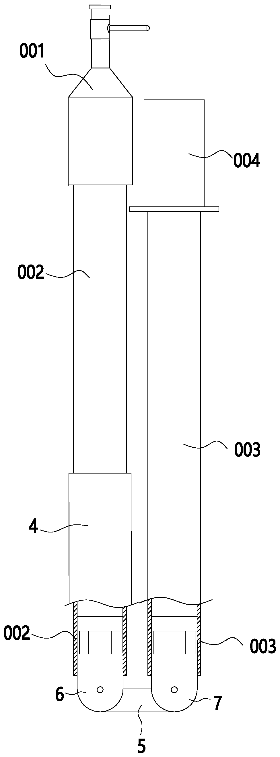
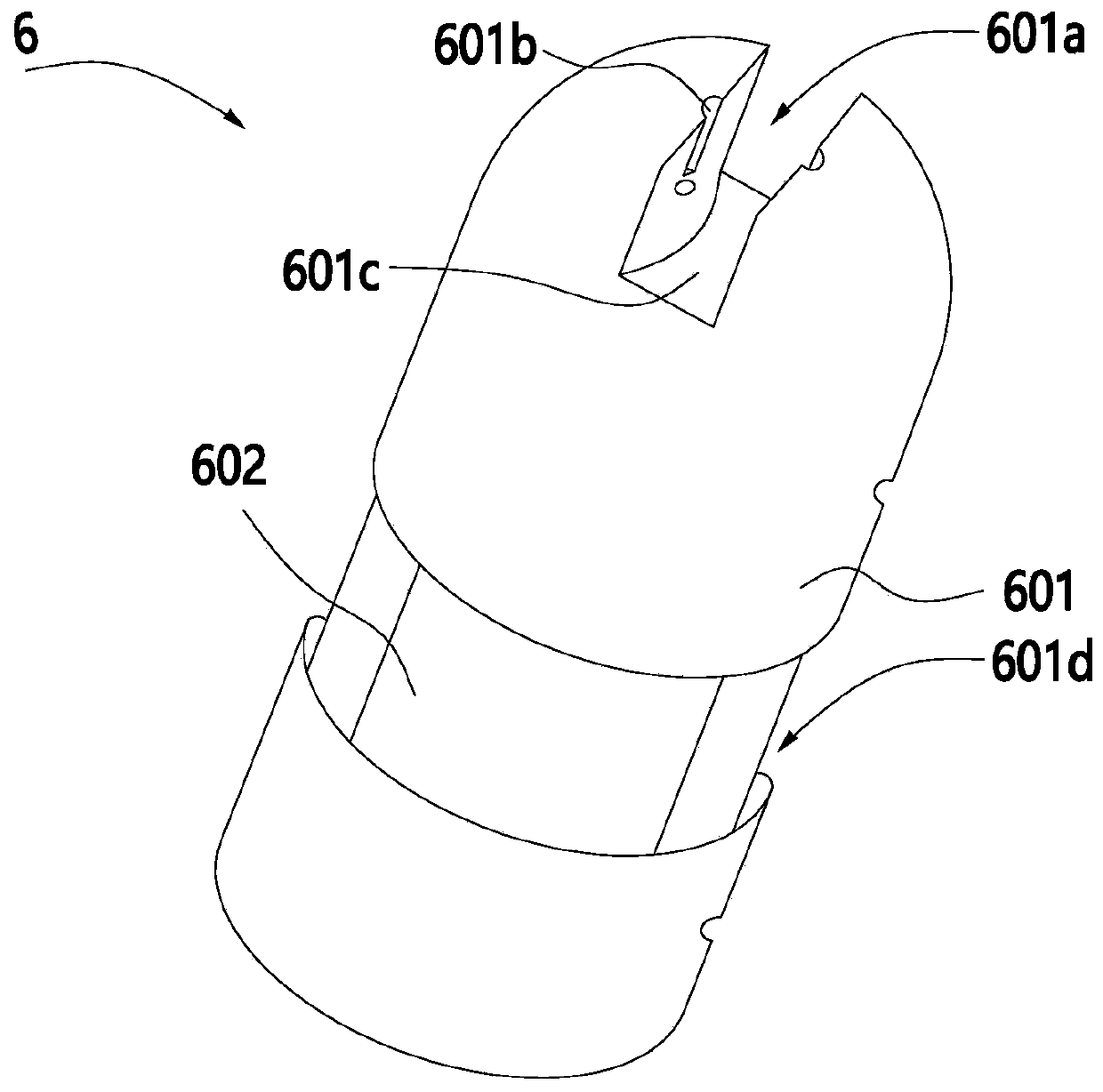
[0040] Such as Figure 1 to Figure 6 As shown, a foldable brake lever movable connection assembly, the brake lever includes a first insulating rod 002 and a second insulating rod 003, the movable connection assembly includes a metal locking sleeve 4, a connecting plate, and is partially inserted and fixed on the first The first magnetic connector 6 at one end of the insulating rod 002 is partially inserted and fixed on the second magnetic connector 7 at one end of the second insulating rod 003. One end of the connecting plate is hinged with the first magnetic connecting head 6, and the other end of the connecting plate is connected with the second magnetic connector. The magnetic connector 7 is hinged, and the shutter lever includes an open mode and a folded mode, and the shutter lever is in the folded mode, such as figure 2 As shown, 4 metal locking sleeves are sleeved on the first insulating rod 002, and the brake lever is in the open mode, as shown in figure 1 As shown, t...
Embodiment 2
[0058] A foldable brake lever, including a working head 001, a first insulating rod 002, and a second insulating rod 003, the working head 001 includes a support rod 1 and an operating cross bar 2, and a connecting sleeve 3 is fixed under the support rod 1, connected The sleeve 3 is sleeved and riveted on the top of the first insulating rod 002, the movable connection assembly described in the above embodiment is provided between the first insulating rod 002 and the second insulating rod 003, and the lower end of the second insulating rod 003 is provided with Rubber grip 004.
[0059] It can be understood that the insulating rods of the foldable switch rod are not limited to two insulating rods, and three or more insulating rods can be provided with annular limiting ribs 9 as required, and adjacent insulating rods are connected by the above-mentioned movable connection assembly. .
[0060] The above is only a specific embodiment of the invention, but the scope of protection o...
Embodiment 3
[0062]The method for using the foldable brake lever in the above embodiment includes the following steps:
[0063] S1: When you need to use the brake lever, turn the first insulating rod 002 and the second insulating rod 003 so that the first insulating rod 002, the second insulating rod 003 are in the same line as the connecting plate, and the first insulating rod 002 is located on the second Above the insulation rod 003;
[0064] S2: Move the metal locking sleeve 4 downwards so that the metal locking sleeve 4 slides from the first insulating rod 002 to the second insulating rod 003 so that the two ends of the metal locking sleeve 4 are respectively sleeved on the first insulating rod 002 and the second insulating rod 003. The second insulating rod 003 is magnetically connected with the first magnetic connector 6 and the second magnetic connector 7 respectively, so that the brake lever is in an open mode;
[0065] S3: After use, slide the metal locking sleeve 4 upwards to di...
PUM
 Abstract
Description
Claims
Application Information
 - R&D
- Intellectual Property
- Life Sciences
- Materials
- Tech Scout
- Unparalleled Data Quality
- Higher Quality Content
- 60% Fewer Hallucinations
Browse by: Latest US Patents, China's latest patents, Technical Efficacy Thesaurus, Application Domain, Technology Topic, Popular Technical Reports.
© 2025 PatSnap. All rights reserved.Legal|Privacy policy|Modern Slavery Act Transparency Statement|Sitemap|About US| Contact US: help@patsnap.com


