
A mobile device for steel pipe welding of steel pipe tower

A mobile device, tower steel pipe technology, applied in the direction of lifting device, lifting frame, etc., can solve the problems of difficult forklift operation, high construction risk, large manpower consumption, etc., and achieves compact structure, good moving stability, and reasonable arrangement. Effect

Active Publication Date: 2021-10-22
STATE GRID HENAN ELECTRIC POWER ELECTRIC POWER SCI RES INST +3
View PDF1 Cites 0 Cited by
  • Summary
  • Abstract
  • Description
  • Claims
  • Application Information

AI Technical Summary

Problems solved by technology

[0002] At the installation and construction site of the steel pipe tower, the steel pipes need to be welded together, but when they are unloaded from the carrier, the steel pipes are usually placed side by side. The existing more commonly used methods are generally to use forklifts or manual handling. The construction cost of using forklifts is high, the operation of forklifts is difficult, and it is easily restricted by the site environment, and it is inconvenient to move; Large amount, low construction efficiency, high construction risk, and inconvenient operation, which cause a lot of inconvenience to related construction procedures
The Chinese invention patent application with the publication number CN110550318A discloses a mobile device for steel pipe welding of a steel pipe tower, which includes two oppositely arranged mobile frames and a support beam arranged between the two mobile frames for connecting the two mobile frames; The frame includes a support frame, a walking wheel arranged at the bottom of the support frame, and a lifting part arranged on the support frame; the support frame is U-shaped with the opening set downward, including horizontally arranged beams and vertical columns arranged on both sides of the bottom of the beam , the walking wheels are installed at the bottom of the column in rotation; the lifting components include a jack set on the beam, a lifting rod, and a load rod arranged at the bottom of the lifting rod and perpendicular to the axis of the lifting rod; the lifting rod slides vertically through the beam , the bearing rod is set in the opening of the support frame, the top of the lifting rod is horizontally provided with an end rod with one end protruding outward, and the top of the piston rod of the jack is set against the bottom surface of the end rod. The invention has simple structure, convenient operation and improved To improve the construction efficiency, but when moving the steel pipe, the telescopic rod must be extended from the casing, and the load rods are respectively extended into the interior of both ends of the steel pipe. When lifting steel pipes of different lengths, it is necessary to adjust the telescopic rod to extend out of the casing before each lifting. The length of the steel pipe is relatively short, the use is complicated, the operation is not easy, and the applicable steel pipe length is relatively short

Method used


Image

  • A mobile device for steel pipe welding of steel pipe tower
  • A mobile device for steel pipe welding of steel pipe tower
  • A mobile device for steel pipe welding of steel pipe tower

Examples


Embodiment 1

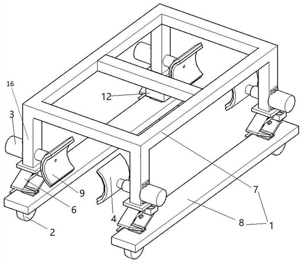
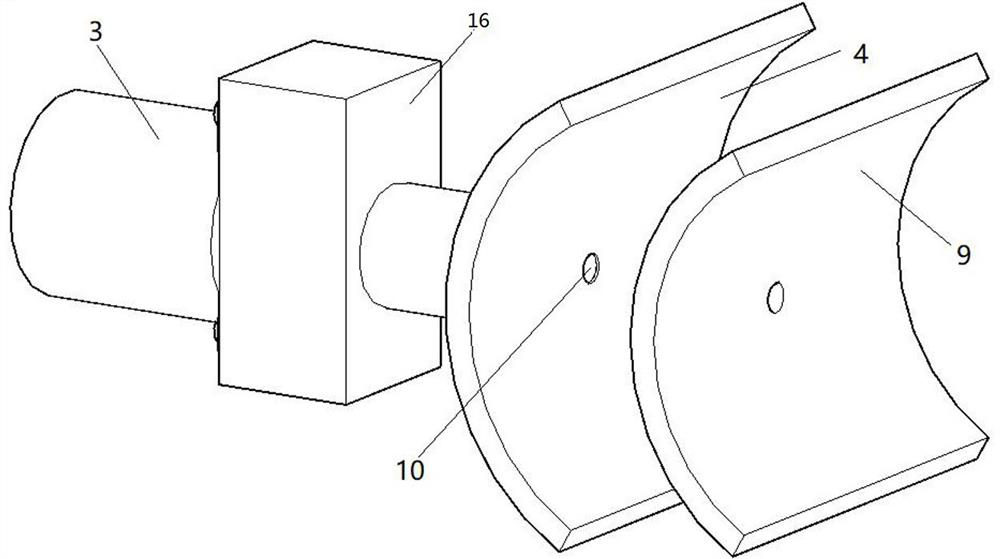
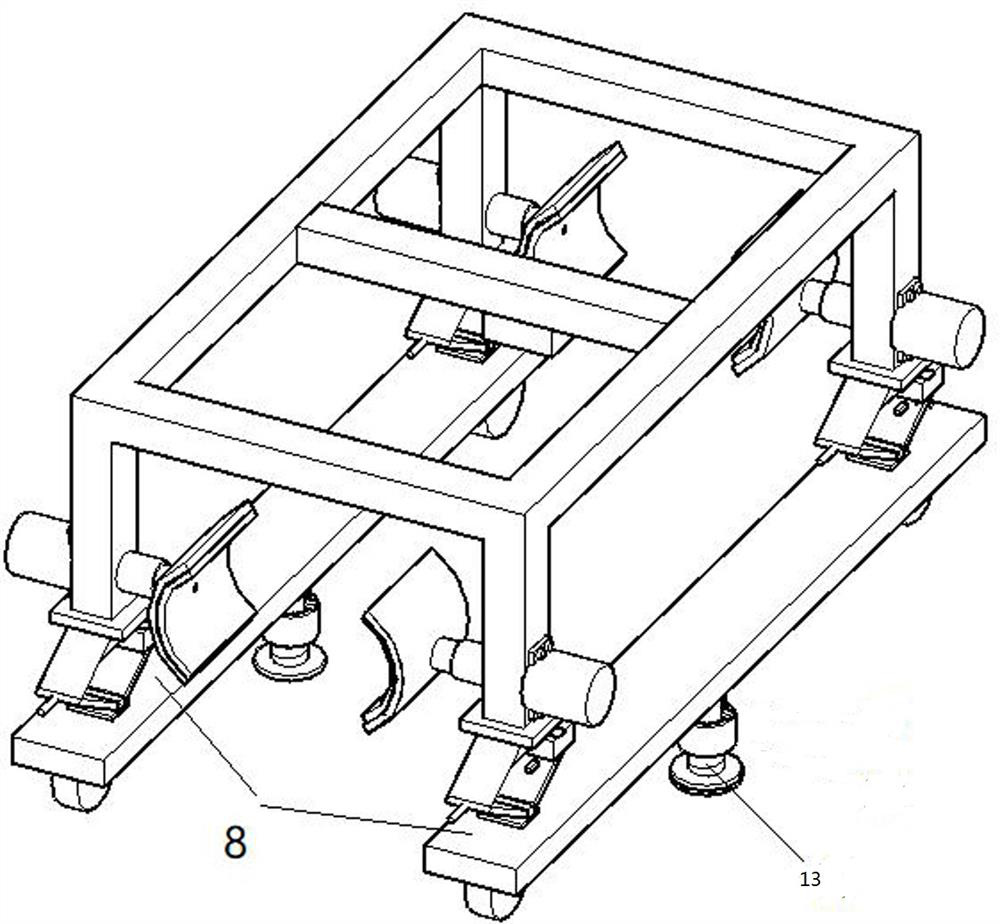
[0032] like Figure 1-2 Shown is the first embodiment of the present invention, a steel pipe welding device, including a fixed frame 1, the fixed frame 1 is composed of an upper fixed frame 7 and a lower fixed frame 8, and the lower fixed frame 8 is two rectangular tubes parallel to each other One, the four corners of the bottom surface of the fixed frame 1 are provided with universal brake wheels 2, that is, universal brake wheels 2 are respectively installed at both ends of the lower end faces of the two rectangular tubes. The upper fixed 7 frame is made up of three rectangular tubes two parallel to each other, two rectangular tubes three welded on two ends of three rectangular tubes two and four vertical bars 16 vertically welded on the bottom end faces of the three rectangular tubes. Four clamping assemblies are arranged symmetrically on the fixed frame 1, and the clamping assembly includes an electric push rod 3 and an arc-shaped plate 4 fixed on the end of the electric p...

Embodiment 3

[0038] like Image 6 Shown is the third embodiment of the present invention. The difference between this embodiment and the first embodiment is that the arc-shaped plate 4 is detachably connected to the end of the electric push rod 3, and the end of the electric push rod 3 is welded with an open end. Cylinder 24, inside the cylinder 24, an internal thread is machined by a lathe, and a round rod 25 is welded to the center of the outer peripheral surface of the arc-shaped plate 4, and an external thread matching the internal thread is processed on the outer peripheral surface of the round rod 25 through a die. The matching of the internal thread and the external thread realizes the detachable connection between the arc plate 4 and the electric push rod 3 .

Embodiment 4

[0040] like Figure 7-8 Shown is the fourth embodiment of the present invention. The difference between this embodiment and Embodiment 1 is that two cross bars 14 are welded on the top of the upper fixing frame 7, and two slide blocks 15 are slidably connected on each cross bar 14. Block 15 is a cuboid block structure with a round hole processed by a lathe inside. The sliding bearing 26 is fixed by glue in the round hole. Sliding, the lower end surface of the slider 15 vertically fixes the vertical plate 27 by means of glue, etc., and the drive assembly that drives the slider 15 to move relatively or oppositely at the same time is set on the fixed frame 1. The drive assembly includes a rotating rod 28, which is rotatably connected to the slider On the block 15, the concave frame 29 is fixed by viscose on the left side of the slide block 15, and the rotating rod 28 is connected in the concave frame 29 by the rotation of the circular shaft. Break away from concave frame 29. Th...


PUM


Abstract

The invention discloses a mobile device for steel pipe welding of a steel pipe tower, which comprises a fixed frame, and multiple groups of clamping assemblies are arranged symmetrically on the fixed frame, and the clamping assemblies include an electric push rod and an arc arranged at the end of the electric push rod. The arc-shaped plates are located on both sides of the steel pipe, the steel pipe is clamped between the arc-shaped plates, the driving device for driving the clamping assembly to move up and down is arranged on the fixed frame, and the universal brake is arranged at the bottom of the fixed frame The two arc-shaped plates hold the steel pipe tightly under the action of the electric push rod, lift the steel pipe to be welded from the ground and move it to the welding place, which is easy to operate.

Description

technical field [0001] The invention relates to the technical field of steel pipe welding, in particular to a mobile device for steel pipe welding of a steel pipe tower. Background technique [0002] At the installation and construction site of the steel pipe tower, the steel pipes need to be welded together, but when they are unloaded from the carrier, the steel pipes are usually placed side by side. The existing more commonly used methods are generally to use forklifts or manual handling. The construction cost of using forklifts is high, the operation of forklifts is difficult, and it is easily restricted by the site environment, and it is inconvenient to move; Large amount, low construction efficiency, high construction risk, and inconvenient operation, which cause a lot of inconvenience to related construction procedures. The Chinese invention patent application with the publication number CN110550318A discloses a mobile device for steel pipe welding of a steel pipe tow...

Claims


Application Information

Patent Timeline
Patent Type & Authority Patents(China)
IPC IPC(8): B66F7/10B66F7/14B66F7/28
CPCB66F7/10B66F7/14B66F7/28
Inventor 耿进锋王超时洪飞姚德贵肖寒马磊崔大田马东方赵理王晓晨张武能
Owner STATE GRID HENAN ELECTRIC POWER ELECTRIC POWER SCI RES INST
Learn More