Manufacturing method of prefabricated assembled deep-arc wave-proof wall

A prefabricated assembly and manufacturing method technology, applied in the direction of breakwaters, manufacturing tools, molds, etc., can solve the problems of low qualified rate of steel bar protection layer, difficulty in uniform steel bar spacing, and easy pollution of steel bar skeletons, so as to save the need for reserved hole seals Blocking links, good construction quality, and the effect of reducing labor input

Inactive Publication Date: 2020-08-04
杭州昂创科技有限公司
View PDF6 Cites 2 Cited by
  • Summary
  • Abstract
  • Description
  • Claims
  • Application Information

AI Technical Summary

Problems solved by technology

[0004] The purpose of the present invention is to solve the problems of low qualified rate of steel bar protection layer, difficulty in uniform spacing of steel bars, easy pollution of steel bar skeleton, long turnover period of pedestal and other problems existing in traditional prefabricated anti-wave wall steel bar binding construction; There are problems such as large material consumption, many formwork joints and weak rigidity, crowbar type formwork removal is easy to damage the formwork and anti-wave wall, the quality of the formed anti-wave wall is poor, and the holes need to be sealed later. A prefabricated assembly deep How to make arc wave wall

Method used


Image

  • Manufacturing method of prefabricated assembled deep-arc wave-proof wall
  • Manufacturing method of prefabricated assembled deep-arc wave-proof wall
  • Manufacturing method of prefabricated assembled deep-arc wave-proof wall

Examples


Embodiment Construction

[0056] The present invention will be further described in detail below with reference to the accompanying drawings and examples. The following examples are explanations of the present invention and are not limited to the following examples.

[0057] The invention relates to a method for manufacturing a prefabricated deep circular arc wave wall, which comprises the following steps:

[0058] S1: Make a reinforcement cage based on the finalized tire frame;

[0059] S2: Place the reinforcement cage in the finalized formwork, pour concrete based on the finalized formwork, remove the finalized formwork after the concrete reaches strength, and form a prefabricated deep circular arc wave wall.

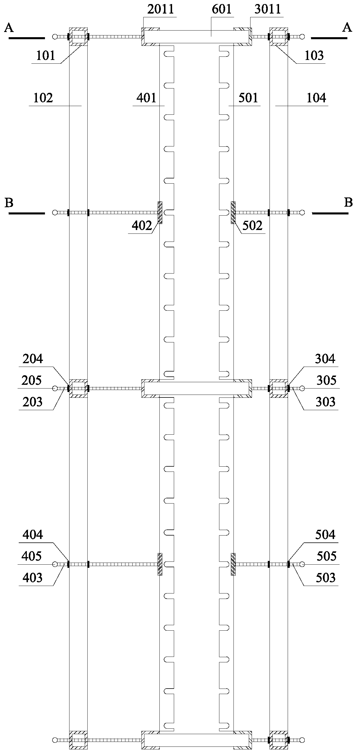
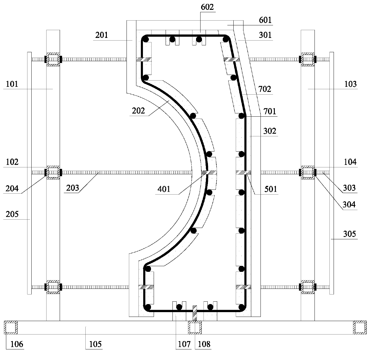
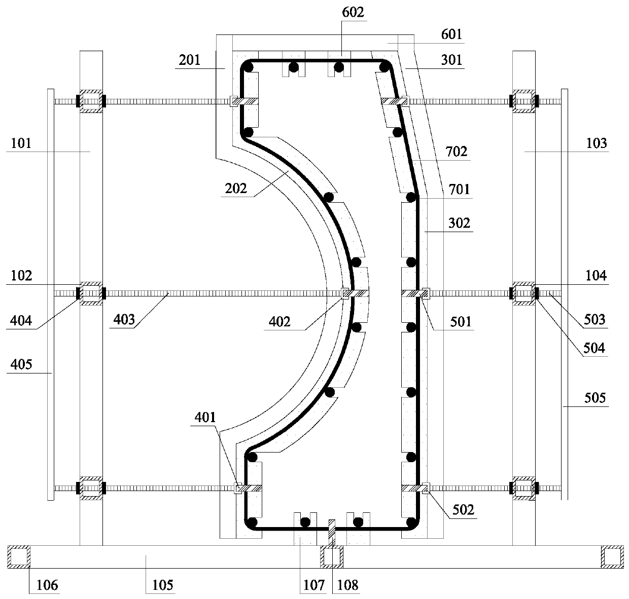
[0060] In step S1, the structure of the integrally formed and finalized tire frame of the deep circular arc anti-wave wall reinforcement cage is as follows: Figure 1~3 As shown, it includes a fixed frame 1, a main rib positioning frame 2 of an arc segment, a main rib positioning frame 3 of a...


PUM


Abstract

The invention relates to a manufacturing method of a prefabricated assembled deep-arc wave-proof wall. The method mainly comprises the steps of mounting a stirrup, adjusting and fixing a shaping moulding bed, installing main ribs and binding a reinforcement cage, machining a table base, hoisting a reinforcement cage, adjusting and fixing a shaping mold frame, pouring concrete, hoisting the wave-proof wall, and installing the wave-proof wall. According to the manufacturing method, the reinforcing cage is bound by utilizing the shaping moulding bed: the stirrup and the main ribs are clamped in detachable positioning frames on the two sides, the reinforcement cage is bound, and the detachable positioning frames are pulled away in a fragment mode and the steel reinforcement cage is hoisted integrally; and the anti-wave wall is poured through the shaping mold frame, the reinforcement cage is hoisted on the upper portion of the table base, sliding mold frames on the two sides slide in placealong guide rails and fixed, the sliding mold frames on the two sides are removed after the pouring of the anti-wave wall is completed, and the anti-wave wall is lifted off. The manufacturing method is simple in process, convenient to construct and high in production efficiency; and the formed wave-proof wall is good in quality and high in mounting precision, and the problems of traditional prefabricated anti-wave wall steel bar binding and concrete pouring construction are solved.

Description

technical field [0001] The invention relates to a method for manufacturing and installing a prefabricated deep circular arc anti-wave wall, which belongs to the field of water conservancy engineering and is suitable for the production and installation of the prefabricated and assembled deep circular arc anti-wave wall. Background technique [0002] Compared with the cast-in-place anti-wave wall, the prefabricated anti-wave wall greatly reduces the material consumption, and the quality of the anti-wave wall structure is easier to control. It can realize standardized and factory prefabricated production, and can be mass-produced without being affected by the natural environment. The structure of the prefabricated anti-wave wall, such as the patent No. CN205557442U, discloses a prefabricated anti-wave wall, which includes a parapet structure, a front block, a rear block, buckles on both sides and a bottom anti-skid plate. The front block and the rear block are respectively arra...

Claims


Application Information

Patent Timeline
IPC IPC(8): B28B7/00B28B23/02B21F27/20E02B3/06
CPCB21F27/20B28B7/0041B28B7/0055B28B23/02E02B3/06
Inventor 陈小林朱凯
Owner 杭州昂创科技有限公司
Why Eureka
Try Eureka