Slitting device for electrolytic copper foil

A technology of electrolytic copper foil and mounting plate, which is applied in the field of electrolytic copper foil slitting device, can solve problems such as aluminum foil is easy to cause quality problems, circuit board short circuit, lithium battery is easy to cause breakdown accidents, etc., to maintain cleaning effect and ensure quality , good cleaning effect

Active Publication Date: 2020-08-04
GUANGDONG FINE YUAN SCI TECH CO LTD
View PDF6 Cites 0 Cited by
  • Summary
  • Abstract
  • Description
  • Claims
  • Application Information

AI Technical Summary

Problems solved by technology

[0003] During the slitting process of electrolytic copper foil, the vibration of the cutting device, the condition of the cutting tool, and the relative movement between the copper foil and the cutting device will cause copper powder to be produced during the slitting process. If these copper powders are not treated in time After processing, the copper powder produced by slitting will adhere to the surface of the copper foil, causing these aluminum foils to easily cause quality problems during application, such as breakdown accidents when used in lithium batteries, and short circuits when used on circuit boards. In the production process of copper foil, it is necessary to deal with the copper powder produced in the production process in time to improve the quality of the formed electrolytic copper foil. In the prior art, it is mainly through manual cleaning and mechanical cleaning. The former The cost is high and the efficiency is low. The latter is easy to absorb copper powder after cleaning for a long time, resulting in the gradual decline of the cleaning effect as the cleaning progresses. , an electrolytic copper foil slitting device that ensures the quality of the slit-formed copper foil, the present invention provides the following technical solutions

Method used


Image

  • Slitting device for electrolytic copper foil
  • Slitting device for electrolytic copper foil
  • Slitting device for electrolytic copper foil

Examples


Embodiment Construction

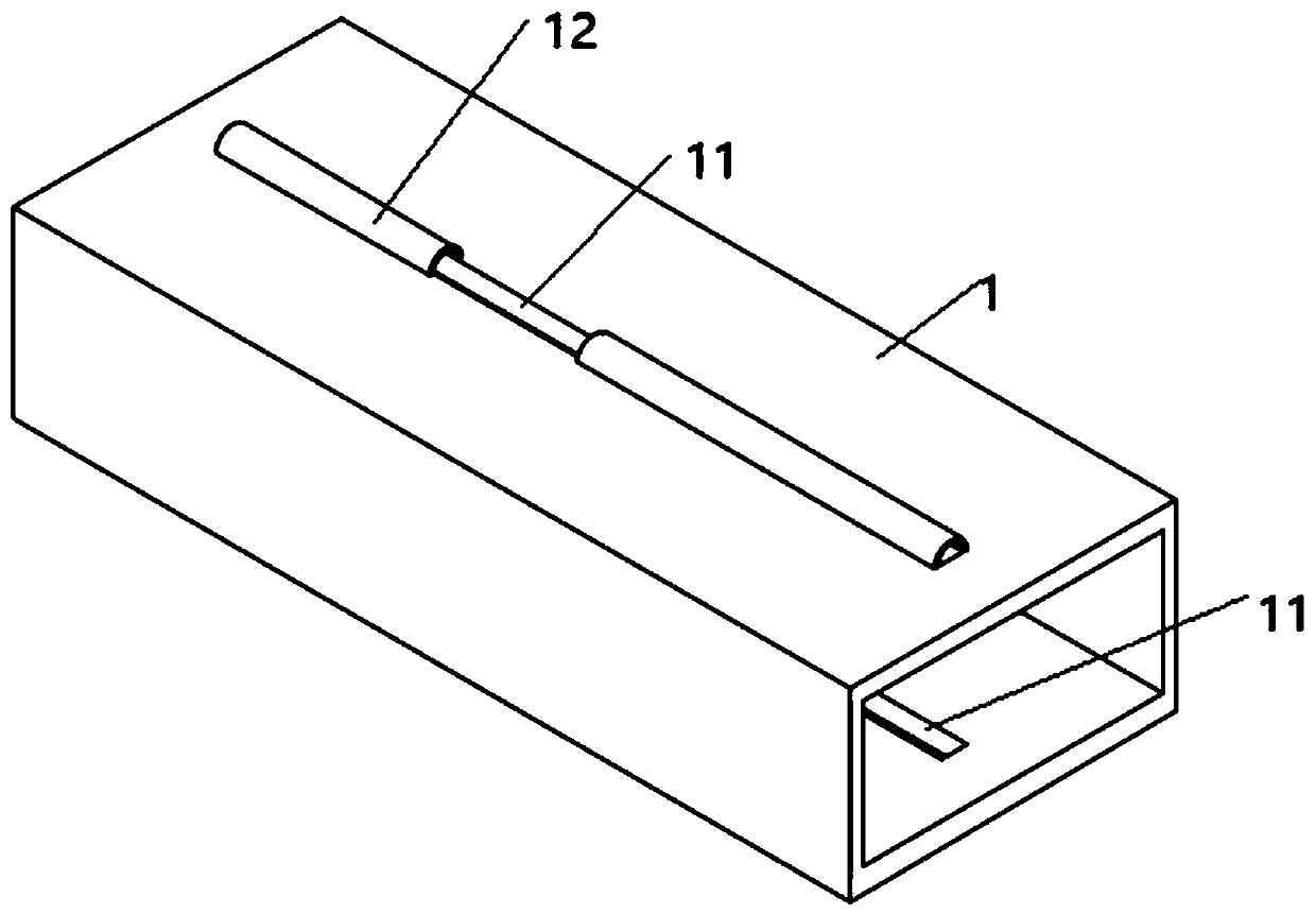
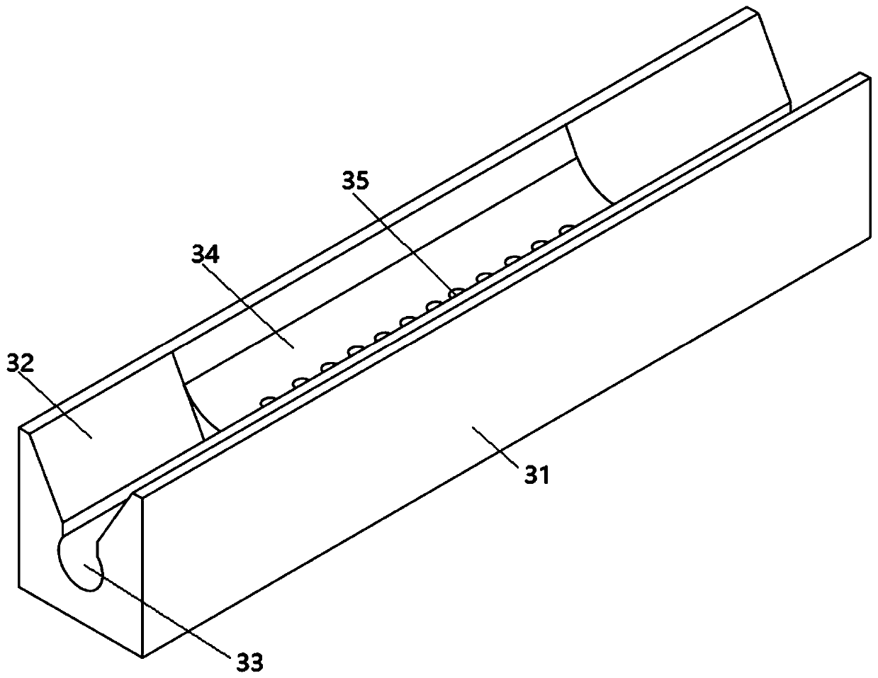
[0032] see Figure 1-8 , describe in detail in conjunction with the following examples:

[0033] An electrolytic copper foil cutting device, such as figure 1 As shown, it includes a casing 1 with openings at both ends, a sealed guide roller 2 fixedly installed at both ends of the opening of the casing 1, and a dust collecting seat 3 fixedly installed in the casing 1, which is arranged above the dust collecting seat 3 and connected to the casing. 1 Rotatingly connected cutting roller 4, a cutting knife 5 arranged above the cutting roller 4 and slidingly connected with the casing 1, a first dust removal roller 6 and a second dust removal roller 7 arranged on one side of the dust collecting seat 3, The first dust removal roller 6 and the second dust removal roller 7 are rotatably installed on the casing 1, the first dust removal roller 6 is arranged above the second dust removal roller 7, and a guide roller 8 is also rotatably installed in the casing 1, and the guide roller 8 is...


PUM


Abstract

The invention discloses a slitting device for an electrolytic copper foil. The slitting device for the electrolytic copper foil comprises a machine shell with openings in the two ends, sealing guide rollers fixedly installed at the two ends of the openings of the machine shell, a dust collecting base fixedly installed in the machine shell, a cutting carrier roller arranged above the dust collecting base and rotationally connected with the machine shell, a cutting tool arranged above the cutting carrier roller and slidably connected with the machine shell, and a first dust removing roller and asecond dust removing roller arranged on one side of the dust collecting base, wherein the first dust removing roller and the second dust removing roller are rotationally installed on the machine shell, and the first dust removing roller is arranged above the second dust removing roller. In the whole working process of the slitting device, on one hand, copper powder attached to the surface of thecopper foil can be reduced, the attached copper powder is mainly concentrated on the two cut side edges, then the attached copper powder is swept and transferred, the quality of the produced copper foil is guaranteed, the collected copper powder can be transferred in time, and it is guaranteed that after long-time sweeping work is carried out, a good sweeping effect can still be kept.

Description

technical field [0001] The invention belongs to the technical field of electrolytic copper foil processing, and in particular relates to an electrolytic copper foil cutting device. Background technique [0002] Electrolytic copper foil is an important material for the manufacture of copper clad laminates, printed circuit boards, and lithium-ion batteries. The production process of electrolytic copper foil is simple. There are three main processes: solution raw foil, surface treatment and product cutting. The edge of the formed copper foil is cut to form a smooth and flat edge, and then the formed copper foil is rolled and packaged. [0003] During the slitting process of electrolytic copper foil, the vibration of the cutting device, the condition of the cutting tool, and the relative movement between the copper foil and the cutting device will cause copper powder to be produced during the slitting process. If these copper powders are not treated in time After processing, th...

Claims


Application Information

Patent Timeline
Patent Type & Authority Applications(China)
IPC IPC(8): B26D1/03B26D7/02B26D7/24B26D7/18B08B1/02B08B5/02B08B1/00
CPCB08B1/006B08B1/02B08B5/02B26D1/035B26D7/02B26D7/1854B26D7/2614B26D7/2628
Inventor 杨雨平杨剑文刘少华吴国宏王爱军陈正辉张任李志华张健廖飞群郭艳霞
Owner GUANGDONG FINE YUAN SCI TECH CO LTD
Why Eureka
Try Eureka