


Quick Research
Generate reliable direction feasibility study reports for your R&D in just a few steps.

Technical Q&A
Discover and master advanced knowledge NOW. Basics, ideas, possibilities, all at once.

Find Solutions
As an expert in R&D theories, this can generate solutions to your technical problems instantly.

Evaluate Feasibility
Analyze your overall solution with one click, know your potential R&D risks in advance.

Monitor Landscape
Get weekly tech updates, stay abreast of the latest tech innovations and key insights.
Method and device for predicting angle of ankle joint of artificial limb
A prediction method and ankle joint technology, applied in neural learning methods, prostheses, character and pattern recognition, etc., can solve the problems of poor prediction efficiency and accuracy of prediction models, achieve improved prediction accuracy, excellent dynamic characteristics, The effect of reducing the amount of data calculation
- Summary
- Abstract
- Description
- Claims
- Application Information
AI Technical Summary
Problems solved by technology
Method used
Image

Examples
Embodiment 1
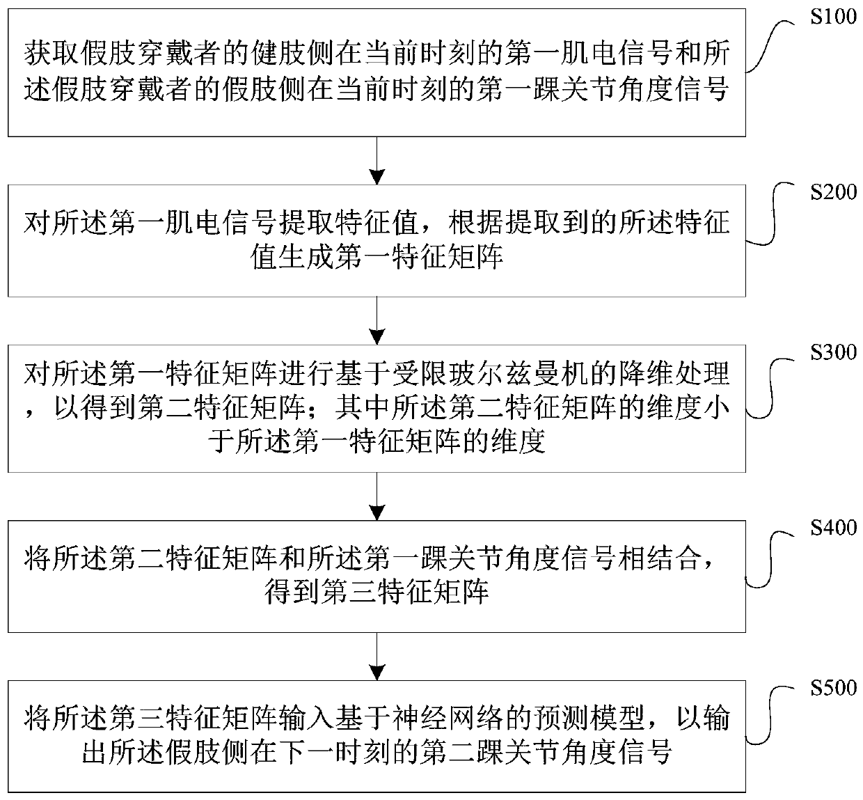
[0065] This embodiment provides a method for predicting the angle of the prosthetic ankle joint, such as figure 1 shown, including the following steps:
[0066] S100: Obtain the first myoelectric signal of the healthy limb side of the prosthesis wearer at the current moment and the first ankle joint angle signal of the prosthesis side of the prosthesis wearer at the current moment.
[0067] This embodiment assumes that one side of the prosthesis wearer's lower limb is the healthy limb, and the other side of the lower limb is the prosthetic limb. Among them, for the healthy limb side, the first myoelectric signal at the calf muscle position can be collected by the myoelectric signal sensor, such as the corresponding myoelectric signal at the position of the lateral gastrocnemius, medial gastrocnemius, tibialis anterior muscle, and peroneus longus; for the prosthetic side, The acceleration of the calf and foot in gait can be collected by the acceleration sensor, and the corresp...
Embodiment 2
[0130] This embodiment provides a prosthetic ankle angle prediction device 100, such as Figure 9 As shown, it includes a signal acquisition unit 101, a feature matrix unit 102, a dimensionality reduction unit 103, a combination unit 104 and a prediction unit 105, wherein:
[0131] The signal acquisition unit 101 is adapted to acquire the first myoelectric signal of the healthy limb side of the prosthesis wearer at the current moment and the first ankle joint angle signal of the prosthesis side of the prosthesis wearer at the current moment;
[0132] Feature matrix unit 102 is adapted to extract feature value to described first myoelectric signal, generates the first feature matrix according to the described feature value extracted;
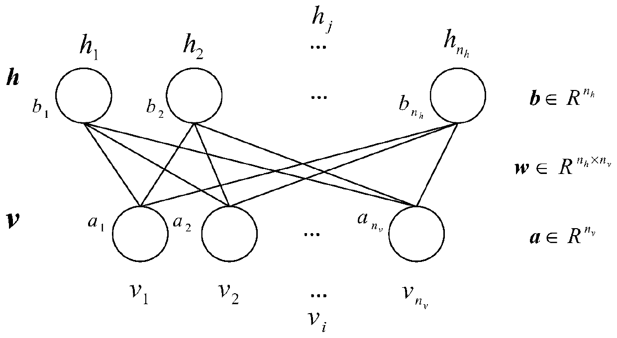
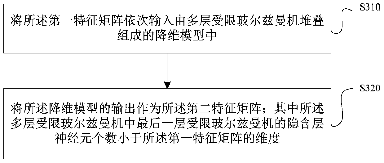
[0133] The dimensionality reduction unit 103 is adapted to perform dimensionality reduction processing based on a restricted Boltzmann machine on the first feature matrix to obtain a second feature matrix; wherein the dimension of the second feat...
Embodiment 3
[0138] This embodiment also provides a computer device, such as a smart phone, a tablet computer, a notebook computer, a desktop computer, a rack server, a blade server, a tower server or a cabinet server (including an independent server, or A server cluster composed of multiple servers), etc. The computer device 20 of this embodiment at least includes but is not limited to: a memory 21 and a processor 22 that can communicate with each other through a system bus, such as Figure 10 shown. It should be pointed out that, Figure 10 Only computer device 20 is shown having components 21-22, but it should be understood that implementing all of the illustrated components is not a requirement and that more or fewer components may instead be implemented.
[0139] In this embodiment, the memory 21 (that is, a readable storage medium) includes a flash memory, a hard disk, a multimedia card, a card-type memory (for example, SD or DX memory, etc.), random access memory (RAM), static ra...
PUM
 Abstract
Description
Claims
Application Information
 - R&D Engineer
- R&D Manager
- IP Professional
- Industry Leading Data Capabilities
- Powerful AI technology
- Patent DNA Extraction
Browse by: Latest US Patents, China's latest patents, Technical Efficacy Thesaurus, Application Domain, Technology Topic, Popular Technical Reports.
© 2024 PatSnap. All rights reserved.Legal|Privacy policy|Modern Slavery Act Transparency Statement|Sitemap|About US| Contact US: help@patsnap.com