Fuel injection valve assembly

A fuel injection valve and component technology, which is applied in the field of high-pressure common rail fuel injection, can solve the problems of limited working pressure of the injector, increased leakage risk of the contact surface, and high difficulty in manufacturing and processing, so as to reduce the opening delay time and improve the service life. , The effect of reducing the difficulty of processing

Inactive Publication Date: 2020-07-31
CHANGSHU INSTITUTE OF TECHNOLOGY
View PDF8 Cites 0 Cited by
  • Summary
  • Abstract
  • Description
  • Claims
  • Application Information

AI Technical Summary

Problems solved by technology

[0002] The control valve is an important part of the fuel injector. It can accurately control the opening of the fuel injector and is the key factor affecting the precise control of the fuel injector. Now the injection pressure requirements of the fuel injector are constantly increasing, and the injection pressure is required to be above 200MPa. At the same time, the hydraulic pressure in the cavity of this type of control valve is also continuously increasing. The oil in the control cavity drops from a high pressure (200MPa and above) to 0MPa, which will cause cavitation damage. The higher the oil pressure, the more serious the cavitation damage. The easier the oiler is damaged, the shorter the service life
[0003] In the prior art, for example, the patent structure of the publication number: CN103967666B does not have a structure for controlling the pressure drop of the chamber, and high pressure will cause cavitation damage, thereby limiting the working pressure of this type of injector; publication number: DE10190272B4 patent technical manual attached Image 6 The restrictor (148) and socket valve (302) shown in the figure can reduce cavitation damage, but there are many sealing contact surfaces between parts, which increases a certain leakage risk; publication number: CN101595297B patent end The ball seat valve (110) also has an inlet (122) with a pre-throttling device (126) and a diffuser (128) arranged between the pre-throttle device (126) and the valve seat (120). ), the diffuser (128) can play a pressure buffer role for high oil pressure, the pressure in the diffuser (128) decreases, and the pressure difference after the outflow in the diffuser (128) decreases, reducing cavitation damage, The one-piece structure in this patent is as attached to its description figure 2 As shown, it is a thin hole at both ends and a thick hole in the middle, so the difficulty of manufacturing and processing is very high, and the diffuser (128) of the split structure in this patent is as attached to its description. image 3 As shown, the difficulty of processing is reduced, but a sealing contact plane is added, which also increases the risk of leakage

Method used


Image

  • Fuel injection valve assembly
  • Fuel injection valve assembly
  • Fuel injection valve assembly

Examples


Embodiment 1

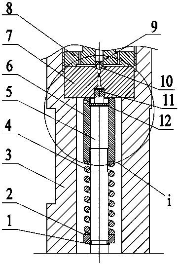
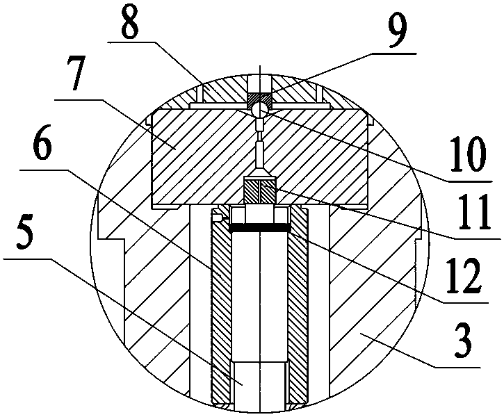
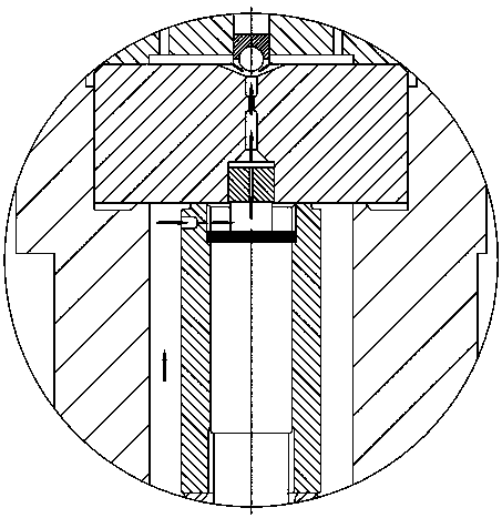
[0029] Example 1, please combine Figure 1 to Figure 3 As shown, the fuel injection valve components involved in this embodiment, such as figure 1 As shown, it includes a control plunger 5, a valve sleeve 6, an orifice 7 and a fastening valve seat 8. The fastening valve seat 8 and the injector body 3 are fixed by threaded connection, and the orifice plate 7 is fixed to the injector body 3. Inside, the valve sleeve 6 is sleeved on the outer circumference of the control plunger 5 to cooperate with the control plunger 5 , and the gap between the valve sleeve 6 and the control plunger 5 is between 0.008mm and 0.012mm. The valve sleeve spring 4 acts on the lower end surface of the valve sleeve 6, and the upper end surface of the valve sleeve 6 abuts against the lower end surface of the orifice plate 7. At this time, the control plunger 5, the valve sleeve 6 and the orifice plate 7 form a control cavity. The side wall of the valve sleeve 6 is provided with an oil inlet hole commun...


PUM


Abstract

The invention discloses a fuel injection valve assembly which comprises an injector body, a control plunger, a valve sleeve, a pore plate and a fastening valve seat; the pore plate, the valve sleeve and the control plunger define a control accommodating cavity; the fuel injection valve assembly further comprises a pressure releasing floating column; a radial raised line is arranged on the upper end face of the control plunger; a gap part at the lower end of the pressure releasing floating column is meshed and connected with the radial raised line in a clamping manner and is arranged on the topsurface of the control plunger; the two ends of the radial raised line protrude out of the side face of the control plunger and are in up-down sliding fit with an inner wall axial sliding chute of the valve sleeve; the inner wall axial sliding chute and a fuel inlet are positioned on the same straight line; a fuel outlet is formed in the other end of the pressure releasing floating column and communicates with the gap part to form a connecting passage; the pore plate is provided with a constraint hole matched with the pressure releasing floating column; the constraint hole communicates with apore plate fuel outlet of the pore plate; and the pressure releasing floating column can move up and down in the constraint hole. The fuel injection valve assembly can solve the problem about cavitation erosion damage of a high-pressure injector, prolongs the service life of the injector and accelerates action response, and fuel flows smoothly.

Description

technical field [0001] The invention relates to a control valve component, in particular to a fuel injection valve component, and belongs to the technical field of high-pressure common rail fuel injection. Background technique [0002] The control valve is an important part of the fuel injector. It can precisely control the opening of the fuel injector and is the key factor affecting the precise control of the fuel injector. Now the injection pressure requirements of the fuel injector are constantly increasing, and the injection pressure is required to be above 200MPa. At the same time, the hydraulic pressure in the cavity of this type of control valve is also continuously increasing. The oil in the control cavity drops from high pressure (200MPa and above) to 0MPa, which will cause cavitation damage. The higher the oil pressure, the more serious the cavitation damage. The easier the oiler is damaged, the shorter the service life. [0003] In the prior art, for example, the...

Claims


Application Information

Patent Timeline
Patent Type & Authority Applications(China)
IPC IPC(8): F02M51/06F02M61/06F02M61/16F02M61/18
CPCF02M51/061F02M61/06F02M61/161F02M61/18
Inventor 许广举赵洋李铭迪林玲胡焰彬刘帅
Owner CHANGSHU INSTITUTE OF TECHNOLOGY
Why Eureka
Try Eureka