
Electric sliding one-way security door

A push-pull, one-way technology, used in fire doors, door/window fittings, power control mechanisms, etc., can solve the problems of deformation of the connection of the security door, difficulty in opening the security door, etc., and achieve the effect of avoiding deformation.

Pending Publication Date: 2020-07-31
安徽乐青琴贸易有限公司
View PDF9 Cites 0 Cited by
  • Summary
  • Abstract
  • Description
  • Claims
  • Application Information

AI Technical Summary

Problems solved by technology

[0004] For the existing electric push-pull one-way security door, due to the high temperature of the fire scene in the event of a fire, the closed security door will expand under the baking of the fire, resulting in deformation of the connection of the security door, making it difficult to Insufficient to open the security door, the present invention provides an electric push-pull one-way security door to solve the above technical problems

Method used


Image

  • Electric sliding one-way security door
  • Electric sliding one-way security door
  • Electric sliding one-way security door

Examples


Embodiment 1

[0027] see Figure 1-Figure 5 :

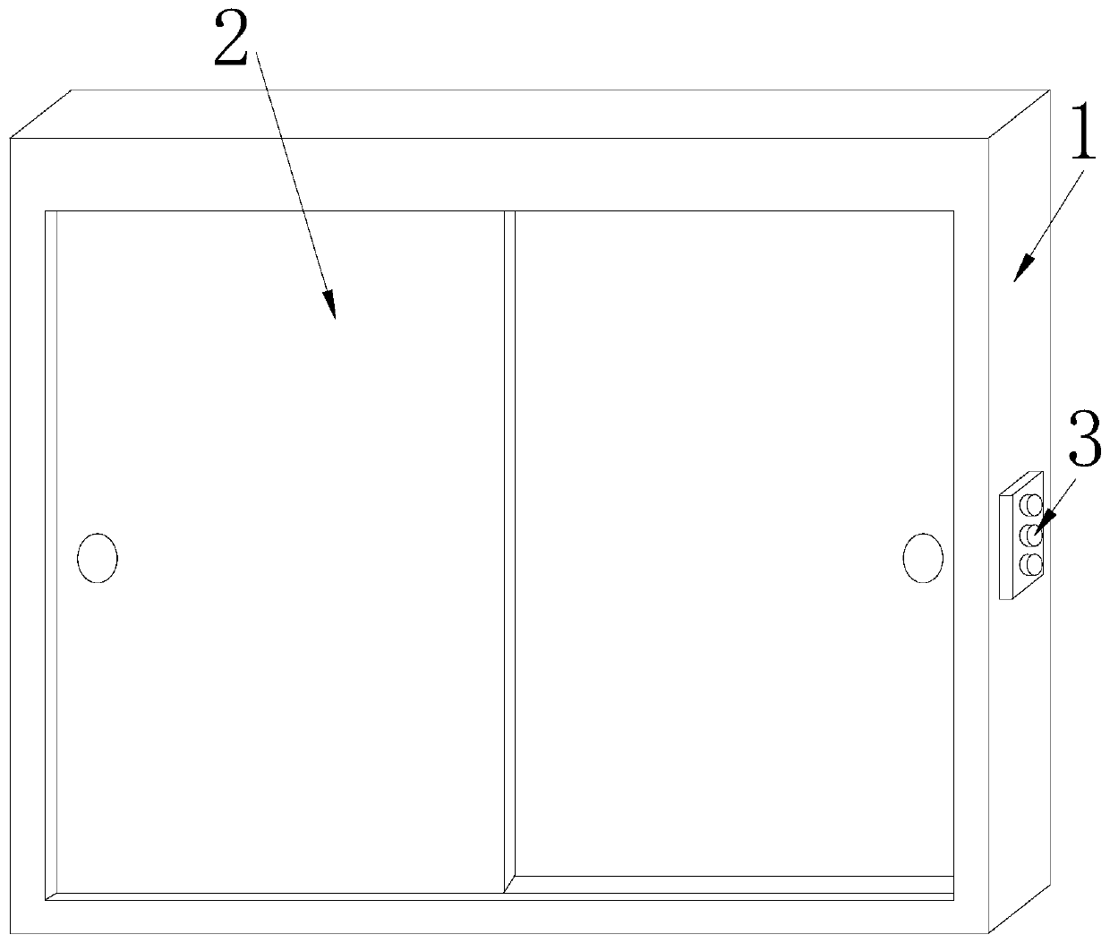
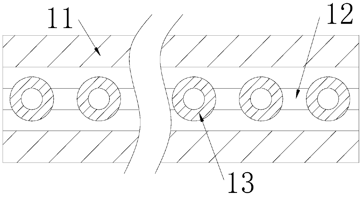
[0028] An electric push-pull one-way security door, its structure includes a door frame 1, a door panel 2, and a control panel 3, the door panel 2 is installed inside the door frame 1, the control panel 3 is connected to the right side of the door frame 1 by welding, the door frame 1 includes a support plate 11, a water pipe 12, and a cooling tank 13. The support plate 11 is embedded in the upper inner wall of the door frame 1. The water pipe 12 is installed inside the support plate 11. The cooling tank 13 is embedded in the water pipe 12. At the bottom, there are multiple cooling grooves 13, which are evenly distributed directly above the door panel 2, which is beneficial to lowering the temperature of the door panel 2.

[0029] In the figure, the cooling tank 13 includes a rotating shaft 131, a water-stop rod 132, a spring 133, and a fuse 134. The rotating shaft 131 is connected to the bottom of the cooling tank 13 through movable engagemen...

Embodiment 2

[0034] see Figure 6-Figure 7 :

[0035] In the figure, the door panel 2 includes a fixed plate 21, a chute 22, a push-pull plate 23, and a slider 24. The fixed plate 21 is embedded in the left side of the door panel 2, and the chute 22 is embedded in the upper and lower inner walls of the door panel 2. , the push-pull plate 23 is installed between the upper and lower chute 22, the slider 24 is connected to the inside of the chute 22 through movable engagement and connected to the upper and lower sides of the push-pull plate 23 by welding, and the fixed plate 21 The inside is provided with an empty groove corresponding to the push-pull plate 23, which is beneficial to the opening and closing of the push-pull plate 23.

[0036] In the figure, the fixed plate 21 includes a motor b1, a rotating rod b2, a gear groove b3, and a positioning rod b4. The motor b1 is embedded in the bottom of the fixed plate 21, and the rotating rod b2 is connected to the top of the motor b1 by weldin...


PUM


Abstract

The invention discloses an electric sliding one-way security door. The security door structurally comprises a door frame, a door plate and a control plate, wherein the door frame comprises a support plate, a water pipe and cooling grooves; each cooling groove comprises a rotating shaft, a water stop rod, a spring and a fuse; each water stop rod comprises a waterproof plug, a fixed block, support blocks and push plates; each support block comprises support springs, a limiting plate and a connecting rod; the door plate comprises a fixed plate, sliding grooves, a push-pull plate and sliding blocks; the fixed plate comprises a motor, a rotating rod, gear grooves and positioning rods; and each positioning rod comprises a positioning cavity, a lifting rod and a positioning plate. The door platesare closed in case of fires to resist smoke and fires. With spread of the fires, the temperature in the fire field rises, the fuses are burnt out by the high temperature, so that the water stop rodsrotate around the rotating shafts clockwise, the waterproof plugs are driven to be separated from the cooling grooves, water in the water pipe is poured to the door plate for cooling treatment, and the difficulty in opening the door plate after the fires are under control due to deformation of the door plate caused by too high temperature is avoided.

Description

technical field [0001] The invention relates to the security field, in particular to an electric push-pull type one-way security door. Background technique [0002] Because the security door has the function of safety and fire prevention, it is widely used in people's lives. When a fire breaks out, closing the security door can play a role in preventing smoke and fire, and provides a guarantee for people's safety. [0003] At present, the existing electric push-pull one-way security door, due to the high temperature of the fire scene in the event of a fire, the closed security door will expand under the baking of the fire, resulting in deformation at the connection of the security door, which makes it difficult for the fire to recede. Open the security door. Contents of the invention [0004] For the existing electric push-pull one-way security door, due to the high temperature of the fire scene in the event of a fire, the closed security door will expand under the baking...

Claims


Application Information

Patent Timeline
Patent Type & Authority Applications(China)
IPC IPC(8): E06B5/16E05F15/635A62C2/24
CPCA62C2/245E05Y2900/134E06B5/16E05F15/635
Inventor 冯家富
Owner 安徽乐青琴贸易有限公司
Learn More