Fuse resistant tolerant of lightning current and pulse current
A technology of pulse current and lightning current, which is applied in the field of electronic components, can solve the problems of large structure and inconvenient installation of external parts, and achieve the effect of convenient and flexible layout, small space occupation, and strong protection against lightning pulse current
- Summary
- Abstract
- Description
- Claims
- Application Information
AI Technical Summary
Problems solved by technology
Method used
Image
Examples
Embodiment 1
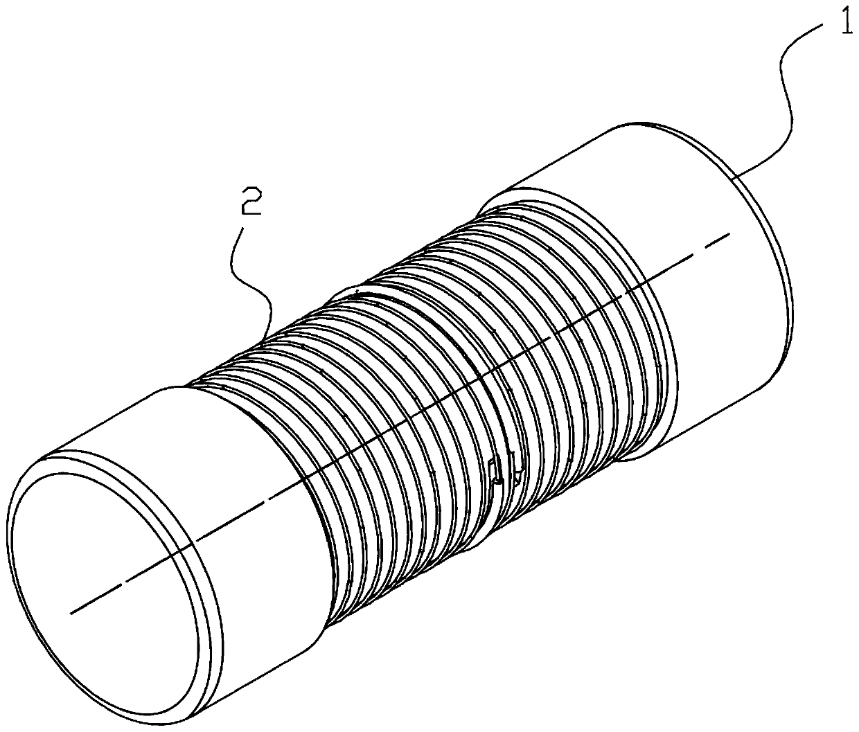
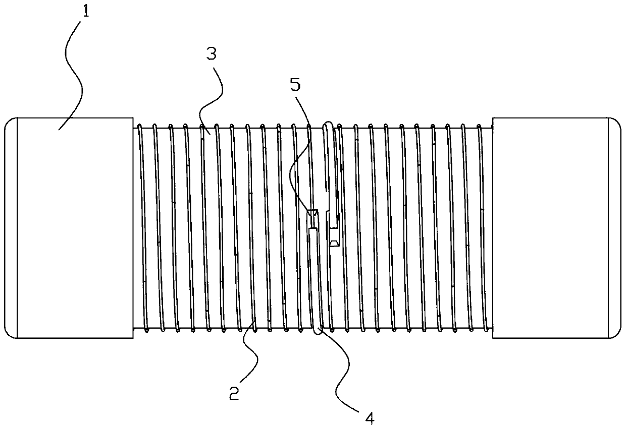
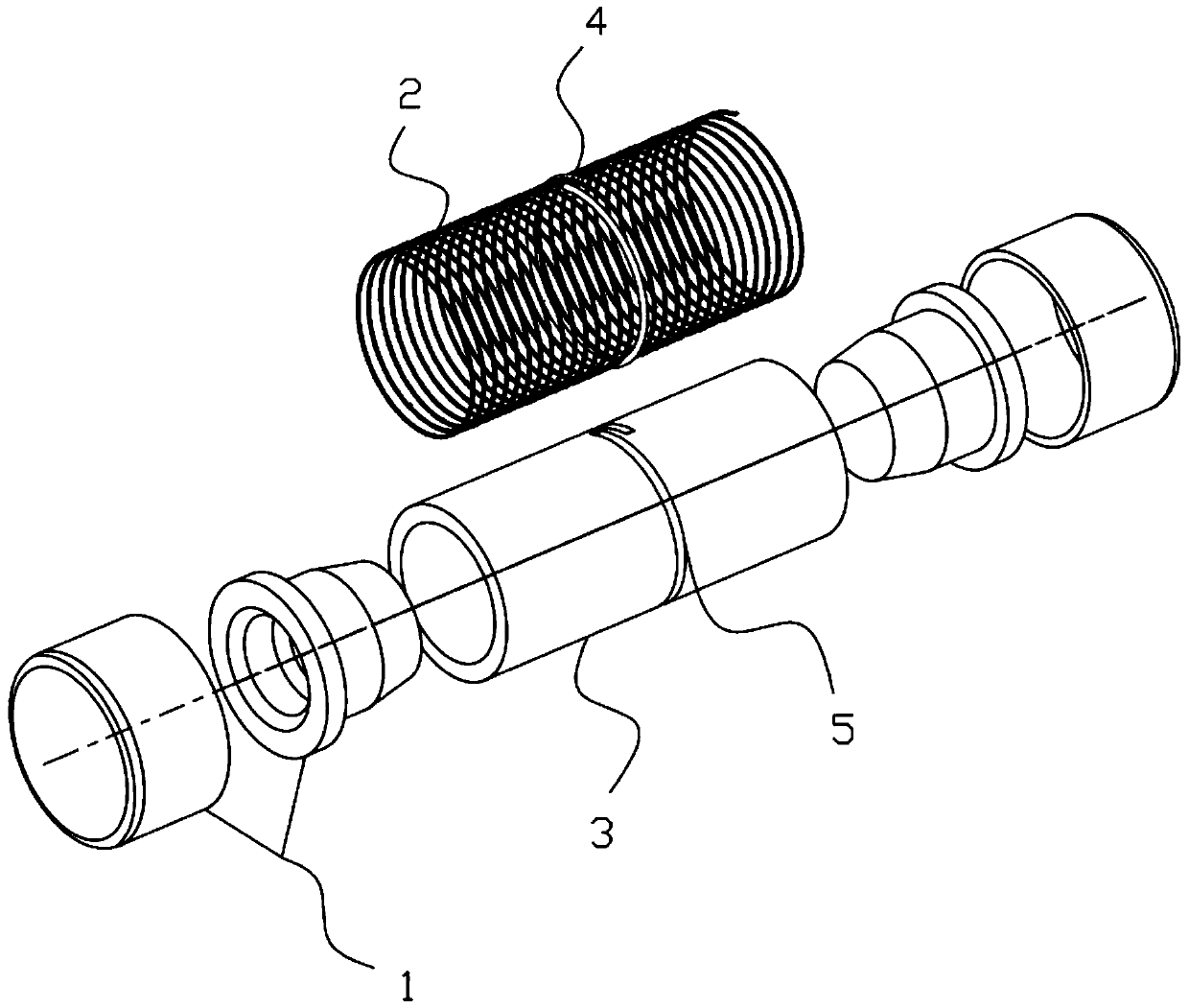
[0047] This embodiment is a fuse capable of withstanding lightning current shocks, such as Figure 1-3 As shown, it mainly includes a cylindrical insulating tube 3 structure, and two openings of the insulating tube 3 are provided with electrode 1 structures for sealing. The electrode 1 is provided with an inwardly recessed protruding part, the protruding part penetrates into the opening of the insulating tube 3, and is bonded to the surface of the ring-shaped flange of the insulating tube 3 and the electrode 1, and in the bonding gap Adhesive insulating glue is provided at the place.
[0048] It can be seen in the figure that when the two symmetrically arranged electrodes 1 are fixed on the opening of the insulating tube 3, there is still a certain distance between the two protruding parts inside, so as to form a gap with the inert gas filled inside the insulating tube 3. discharge gap.
[0049] However, in this embodiment, a structure of a fuse 2 is provided on the outer wa...
Embodiment 2
[0053] This embodiment is a fuse capable of withstanding lightning current impact, which includes a cylindrical insulating tube 3 structure, and two openings of the insulating tube 3 are provided with electrode 1 structures for sealing. The electrode 1 is provided with an inwardly recessed protruding part, which penetrates into the opening of the insulating tube 3, and is bonded to the surface of the ring-shaped flange of the insulating tube 3 and the electrode 1, and is set at the bonding gap. Adhesive insulating glue.
[0054] When the two symmetrically arranged electrodes 1 are fixed on the opening of the insulating tube 3 , there is still a certain distance between the two protruding parts inside, so as to form a discharge gap with the inert gas filled inside the insulating tube 3 .
[0055] Among them, such as image 3 As shown, the outer wall of the insulating tube 3 is provided with a conductive thread structure, and the conductive thread is connected in series with th...
Embodiment 3
[0062] This embodiment is a fuse capable of withstanding lightning current impact, which includes a cylindrical insulating tube 3 structure, and two openings of the insulating tube 3 are provided with electrode 1 structures for sealing.
[0063] The electrode 1 is provided with an inwardly recessed protruding part, which penetrates into the opening of the insulating tube 3, and is bonded to the surface of the ring-shaped flange of the insulating tube 3 and the electrode 1, and is set at the bonding gap. Adhesive insulating glue.
[0064] When the two symmetrically arranged electrodes 1 are fixed on the opening of the insulating tube 3 , there is still a certain distance between the two protruding parts inside, so as to form a discharge gap with the inert gas filled inside the insulating tube 3 .
[0065] A conductive thread structure is provided on the inner wall of the insulating tube 3, and the conductive thread is connected in series with the electrodes 1 on both sides, the...
PUM
 Abstract
Description
Claims
Application Information
 - Generate Ideas
- Intellectual Property
- Life Sciences
- Materials
- Tech Scout
- Unparalleled Data Quality
- Higher Quality Content
- 60% Fewer Hallucinations
Browse by: Latest US Patents, China's latest patents, Technical Efficacy Thesaurus, Application Domain, Technology Topic, Popular Technical Reports.
© 2025 PatSnap. All rights reserved.Legal|Privacy policy|Modern Slavery Act Transparency Statement|Sitemap|About US| Contact US: help@patsnap.com


