Yarn twisting and winding roller fixing device based on bidirectional screw rod transmission principle

A technology of bidirectional screw and fixing device, which is applied in the direction of continuous winding spinning machine, textile and paper making, spinning machine, etc. Line effect, improve work efficiency, improve the effect of line take-up efficiency

Active Publication Date: 2020-07-28
湖南韦闻机械有限公司
View PDF9 Cites 1 Cited by
  • Summary
  • Abstract
  • Description
  • Claims
  • Application Information

AI Technical Summary

Problems solved by technology

[0003] When the twisting machine is twisting, multiple strands of spun yarn are twisted into one strand. However, most of the existing twisting machines place the take-up roller vertically on the twister. However, in this way, the take-up roller will be in contact with the take-up The friction of the wire roller is likely to cause damage to the wire, and the part of the yarn in contact with the mechanical structure is easy to break, and the take-up roller is usually clamped by the bottom clamping device, and it can only be fixed for a single-diameter take-up roller. The diameter of the take-up roller often needs to be prepared with different types of fixing mechanisms. The operation is troublesome, time-consuming and laborious, the fixation is not reliable, and the centering is not accurate. In the process of rotation, it is easy to vibrate due to eccentricity, which affects the efficiency of the take-up line, further increases the friction between the wire and the take-up roller, increases the damage of the wire, and affects the quality of the wire, and the existing twisting machine is only set by setting the alarm. Machines are used to remind workers, so that workers stop for repairs, delay production progress, and it is easy to make products unqualified due to workers’ negligence

Method used


Image

  • Yarn twisting and winding roller fixing device based on bidirectional screw rod transmission principle
  • Yarn twisting and winding roller fixing device based on bidirectional screw rod transmission principle
  • Yarn twisting and winding roller fixing device based on bidirectional screw rod transmission principle

Examples


Embodiment Construction

[0026] The following will clearly and completely describe the technical solutions in the embodiments of the present invention with reference to the accompanying drawings in the embodiments of the present invention. Obviously, the described embodiments are only some, not all, embodiments of the present invention. Based on the embodiments of the present invention, all other embodiments obtained by persons of ordinary skill in the art without making creative efforts belong to the protection scope of the present invention.

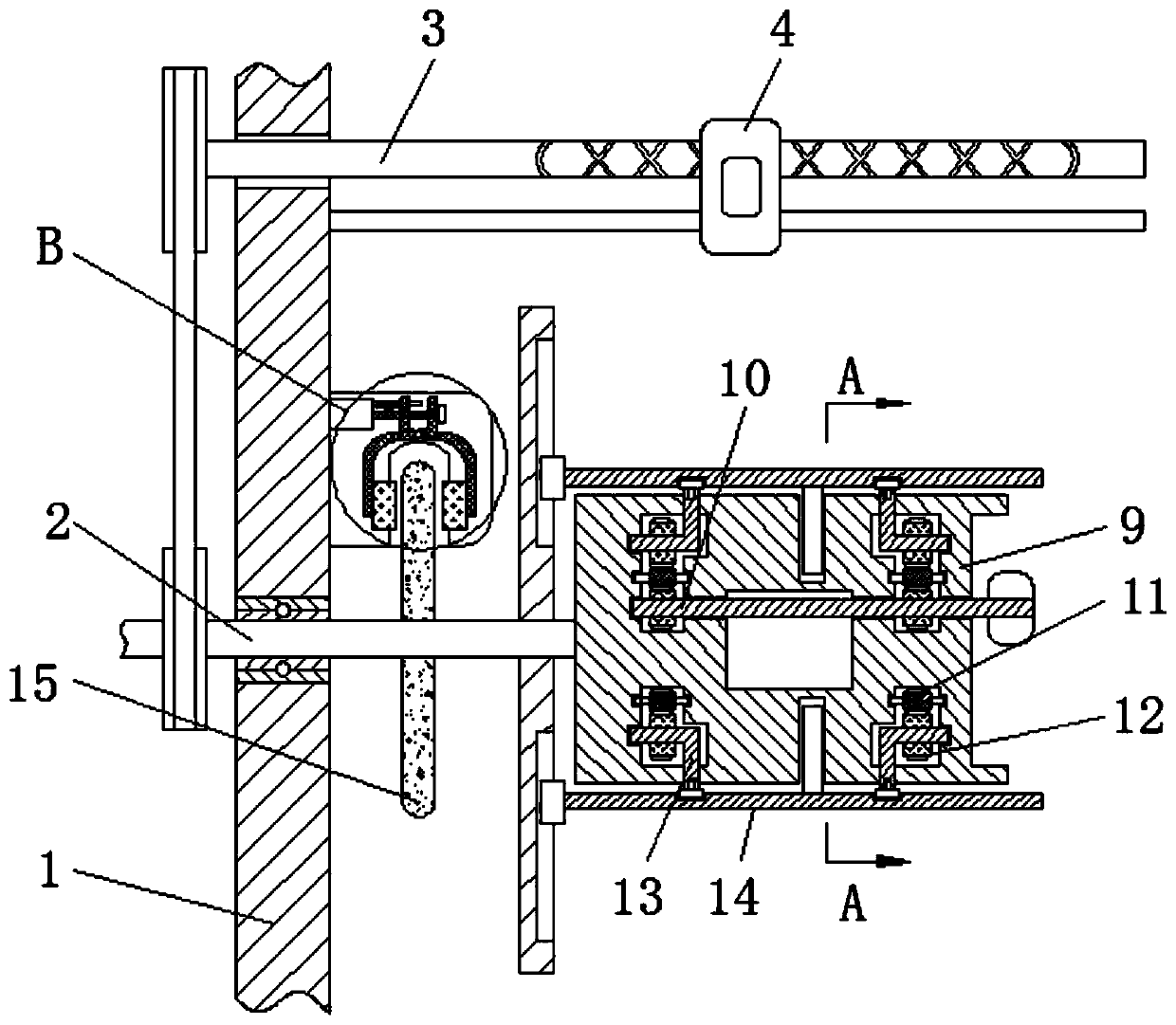
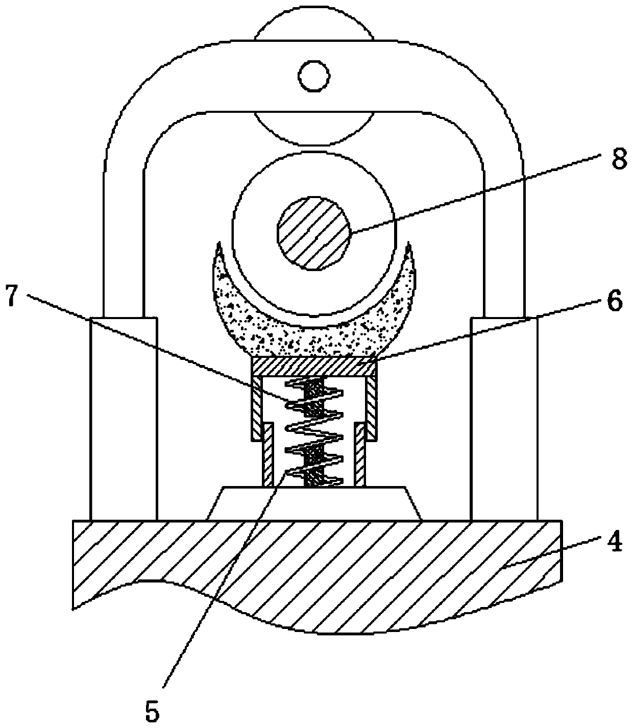
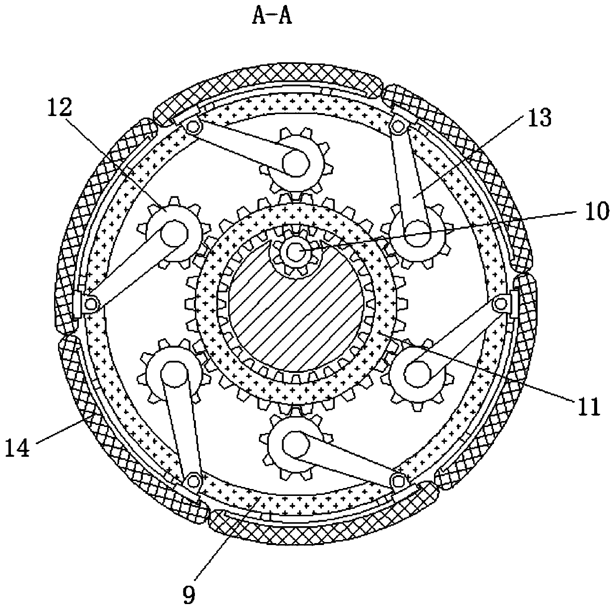
[0027] see Figure 1-4 , a twisting take-up roller fixing device based on the principle of two-way screw drive, including a frame 1, a main shaft 2, a two-way screw 3, a slider 4, a control spring 5, a movable frame 6, an electric contact block 7, and a guide wheel 8, rotating block 9, adjusting lever 10, ring gear 11, fixed gear 12, fixed lever 13, fixed plate 14, brake disc 15, brake lever 16, positioning lever 17, connecting gear 18, movable lever 19, brake...


PUM


Abstract

The invention relates to the technical field of spinning, and discloses a yarn twisting and winding roller fixing device based on a bidirectional screw rod transmission principle. The yarn twisting and winding roller fixing device comprises a machine frame, a main shaft and a directional screw rod are movably connected into the machine frame, a sliding block is movably connected to the exterior ofthe directional screw rod, a control spring is fixedly connected to the exterior of the sliding block, a movable frame is fixedly connected to the exterior of the control spring, the interior of thecontrol spring is in sleeve joint with an electric touch block, a guide roller is movably connected into the movable frame, a rotating block is fixedly connected to the exterior of the main shaft, andan adjusting rod is movably connected into the rotating block. Through the match usage of the main shaft, the bidirectional screw rod, the sliding block and the rotating block, the effect of synchronous guiding in the winding process is achieved, the rotating block is transversely arranged, yarns are effectively prevented from mechanical friction, yarn abrasion is avoided, the winding efficiencyand quality of the yarns are improved, and it is effectively ensured that the yarns are tidily distributed on the winding roller.

Description

technical field [0001] The invention relates to the technical field of textiles, in particular to a fixing device for twisting take-up rollers based on the principle of bidirectional screw rod transmission. Background technique [0002] In the fabric weaving process, it is usually necessary to twist the textile yarn in advance, and the twisting machine is a textile machinery equipment that twists multiple strands of spun yarn into one strand, and its function is to process the yarn or the combined strand yarn product into a linear shape. Products, thread for weaving and knitting, including twisting machine body and circuit part, the spindle outside the twisting machine body is connected with the motor output shaft of the circuit part, and the front end of the spindle is equipped with a connecting piece corresponding to the tap switch. [0003] When the twisting machine is twisting, the multi-strand spun yarn is twisted into one strand. However, most of the existing twisting ...

Claims


Application Information

Patent Timeline
Patent Type & Authority Applications(China)
IPC IPC(8): D01H1/36D01H13/14
CPCD01H1/36D01H13/14
Inventor 何华斌
Owner 湖南韦闻机械有限公司
Why Eureka
Try Eureka