


Quick Research
Generate reliable direction feasibility study reports for your R&D in just a few steps.

Technical Q&A
Discover and master advanced knowledge NOW. Basics, ideas, possibilities, all at once.

Find Solutions
As an expert in R&D theories, this can generate solutions to your technical problems instantly.

Evaluate Feasibility
Analyze your overall solution with one click, know your potential R&D risks in advance.

Monitor Landscape
Get weekly tech updates, stay abreast of the latest tech innovations and key insights.
Resistance type melting furnace and furnace starting method
A resistive and melting furnace technology, applied in electric furnaces, pot furnaces, furnaces, etc., can solve the problems of slow heating rate and large energy consumption, and achieve the effects of fast heating speed, avoiding ablation, and simple structure
- Summary
- Abstract
- Description
- Claims
- Application Information
AI Technical Summary
Problems solved by technology
Method used
Image

Examples
Embodiment 1
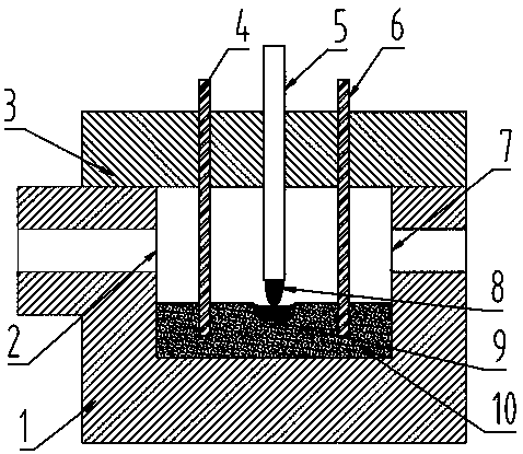
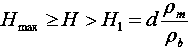
[0046] In this embodiment, a layer of raw material 10 is laid on the bottom of the furnace body 1. The raw material 10 adopts ordinary silicate glass particles with an average particle size of 5 mm. According to the formula
[0047]
[0048] Known ρ b The bulk density of the raw material 10 particles is 1.2t / m 3 ;
[0049] ρ m It is raw material 10 high temperature melting density 2.4t / m 3 ;
[0050] d is the distance 100mm between the bottom of the first electrode 4 and the bottom of the second electrode 6 and the bottom of the furnace body 1;
[0051] h max The height of discharge port 2 from the bottom of furnace body 1 is 400mm;
[0052] h 1 The minimum limit height for laying raw material 10 is 200mm;
[0053] It can be seen that the laying height of the raw material 10 is H=300mm.
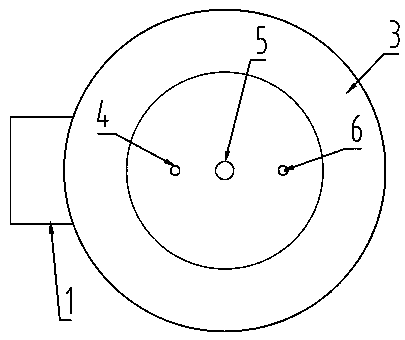
[0054] In this embodiment, the through hole of the plasma torch on the furnace cover is set in the center of the furnace body, the plasma torch is located in the center of the fur...
Embodiment 2
[0063] In this embodiment, a layer of raw material 10 is laid on the bottom of the furnace body 11. The raw material 10 is made of ordinary silicate glass particles with an average particle size of 6 mm. According to the formula
[0064]
[0065] Known ρ b The bulk density of the raw material 10 particles is 1.2t / m 3 ;
[0066] ρ m It is raw material 10 high temperature melting density 2.4t / m 3 ;
[0067] D is the distance 80mm between the bottom of the first electrode 4 and the bottom of the second electrode 6 from the bottom of the furnace body 1;
[0068] h max The height of discharge port 2 from the bottom of furnace body 1 is 400mm;
[0069] h 1 The minimum limit height for laying raw material 10 is 160mm;
[0070] It can be seen from this that the laying thickness of the raw material 10 is H=300mm.
[0071] After the furnace cover 3 is covered, the height of the plasma torch is adjusted so that the bottom of the torch is 100 mm away from the top of the raw ma...
PUM
| Property | Measurement | Unit |
|---|---|---|
| particle diameter | aaaaa | aaaaa |
| electrical resistance | aaaaa | aaaaa |
| particle size | aaaaa | aaaaa |
Abstract
Description
Claims
Application Information
 - R&D Engineer
- R&D Manager
- IP Professional
- Industry Leading Data Capabilities
- Powerful AI technology
- Patent DNA Extraction
Browse by: Latest US Patents, China's latest patents, Technical Efficacy Thesaurus, Application Domain, Technology Topic, Popular Technical Reports.
© 2024 PatSnap. All rights reserved.Legal|Privacy policy|Modern Slavery Act Transparency Statement|Sitemap|About US| Contact US: help@patsnap.com