Displayer metal frame simple in process and manufacturing process and manufacturing equipment thereof

A metal frame, simple process technology, used in metal processing equipment, manufacturing tools, instruments, etc., can solve the problems of unguaranteed quality stability, difficulty in ensuring uniform quality, and increased surface treatment costs, to avoid poor quality stability, reduce Surface treatment costs, the effect of reducing transfer work

Active Publication Date: 2020-07-28
苏州金利美金属科技有限公司
View PDF12 Cites 2 Cited by
  • Summary
  • Abstract
  • Description
  • Claims
  • Application Information

AI Technical Summary

Problems solved by technology

[0002] At present, for display products, consumers not only pursue the quality and function of the product, but also pay more attention to the exquisiteness of the appearance of the product. For this reason, most display manufacturers will use all-metal frames to improve the exquisiteness of their products; and these metal frames The specific processing technology is as follows: the metal sheet / roll material is formed into a U-shaped metal frame strip after being cut, and the single side of the metal frame is obtained after cutting; then the surface appearance of each single piece is treated to meet the appearance of the product Requirements, finally, the metal frame will be obtained by unilaterally assembling after surface treatment; however, this kind of processing process is complicated, the processing cycle is long, and the cost of surface treatment after forming is increased; it is difficult to guarantee the surface treatment of each single piece after cutting. The appearance of each single piece has a uniform quality, resulting in quality stability that cannot be guaranteed; therefore, it is necessary to find a method that can solve such problems

Method used


Image

  • Displayer metal frame simple in process and manufacturing process and manufacturing equipment thereof

Examples


Embodiment Construction

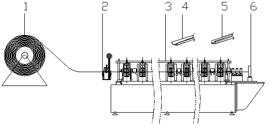
[0029] Embodiments of the present invention are described in detail below, examples of which are shown in the accompanying drawings, wherein the same or similar reference numerals represent the same or similar elements or elements with the same or similar functions; The embodiments are exemplary and are only used to explain the present invention, but not to be construed as limiting the present invention.

[0030] In describing the present invention, it should be understood that the terms "upper", "lower", "bottom", "top", "front", "rear", "inner", "outer", "horizontal", " The orientation or positional relationship indicated by "vertical", etc. is based on the orientation or positional relationship shown in the drawings, which is only for the convenience of describing the present invention and simplifying the description, rather than indicating or implying that the device or element referred to must have a specific orientation, so as to Specific orientation configurations and o...


PUM


Abstract

The invention discloses a displayer metal frame simple in process and a manufacturing process and manufacturing equipment thereof. The manufacturing process comprises the following steps that metal sheets / coils with appearance films on single-side surfaces or dual-side surfaces are prepared, and the appearance films comprise protection layers, or comprise appearance layers and protection layers covering the appearance layers; the metal sheets / or coils are subjected to continuous rolling / bending to form a metal frame strip, and after cutting, a metal frame single side is obtained; and multiplemetal frame single sides are assembled to obtain the metal frame. All raw materials can be directly subjected to unified surface treatment, through the protection layers, surfaces, with appearances, of the metal sheets / coils are prevented from being damaged in the rolling / bending forming process, surface treatment of a single piece can be avoided, a machining procedure is reduced, the surface treatment cost is reduced, product quality stability is ensured, the assembling process is simplified, and the production efficiency is greatly improved.

Description

technical field [0001] The invention relates to the technical field of display frames, in particular to a display metal frame with a simple process and its manufacturing process and manufacturing equipment. Background technique [0002] At present, for display products, consumers not only pursue the quality and function of the product, but also pay more attention to the exquisiteness of the appearance of the product. For this reason, most display manufacturers will use all-metal frames to improve the exquisiteness of their products; and these metal frames The specific processing technology is as follows: the metal sheet / roll material is formed into a U-shaped metal frame strip after being cut, and the single side of the metal frame is obtained after cutting; then the surface appearance of each single piece is treated to meet the appearance of the product Requirements, finally, the metal frame will be obtained by unilaterally assembling after surface treatment; however, thi...

Claims


Application Information

Patent Timeline
IPC IPC(8): B21D53/74B21D5/08B21D43/28B29C63/02G06F1/16
CPCB21D53/74B21D5/08B21D43/285B29C63/02G06F1/1601
Inventor 肖铮韩丁
Owner 苏州金利美金属科技有限公司
Why Eureka
Try Eureka