Eureka AIR delivers breakthrough ideas for toughest innovation challenges, trusted by R&D personnel around the world.

Sleeve kiln local oxygenation system

A sleeve kiln and partial technology, applied in the field of sleeve kiln, can solve the problems of high fuel consumption of low calorific value, large amount of NOx generation, large fuel consumption, etc., to achieve complete combustion, intense combustion process, and reduced oxygen consumption Effect

Pending Publication Date: 2020-07-24
JIANGSU ZHONGSHENGYUAN TECH CO LTD
View PDF0 Cites 1 Cited by
  • Summary
  • Abstract
  • Description
  • Claims
  • Application Information

AI Technical Summary

Problems solved by technology

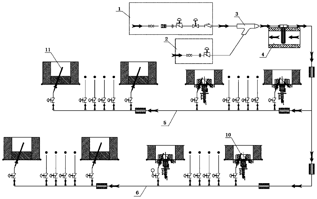
[0005] The purpose of the present invention is to provide a local aeration system for a sleeve kiln, which solves the problems of high fuel consumption, high carbon monoxide (CO) content in flue gas, and low thermal efficiency when low-calorific-value fuel is used, and at the same time avoids the overall Oxygen-enriched combustion temperature is too high and NOx generation is large. By adding oxygen-increasing air pipes, oxygen-increasing air can participate in the fuel combustion of sleeve kiln. Oxygen-increasing air with high oxygen content can be used to partially replace the combustion-supporting gas. Inject less gas, which solves the problems of large consumption of low calorific value fuel, increased flue gas volume, and increased heat loss. At the same time, it improves the combustion intensity of fuel, enhances heat transfer, and controls the generation and emission of NOx

Method used


Image

  • Sleeve kiln local oxygenation system
  • Sleeve kiln local oxygenation system
  • Sleeve kiln local oxygenation system

Examples


Embodiment Construction

[0028] The following will clearly and completely describe the technical solutions in the embodiments of the present invention with reference to the accompanying drawings in the embodiments of the present invention. Obviously, the described embodiments are only some, not all, embodiments of the present invention. Based on the embodiments of the present invention, all other embodiments obtained by persons of ordinary skill in the art without making creative efforts belong to the protection scope of the present invention.

[0029] It should be noted that in this document, relational terms such as first and second etc. are only used to distinguish one entity or operation from another entity or operation, and do not necessarily require or imply that there is a relationship between these entities or operations. There is no such actual relationship or order between them. Furthermore, the term "comprises", "comprises" or any other variation thereof is intended to cover a non-exclusive...


PUM


Abstract

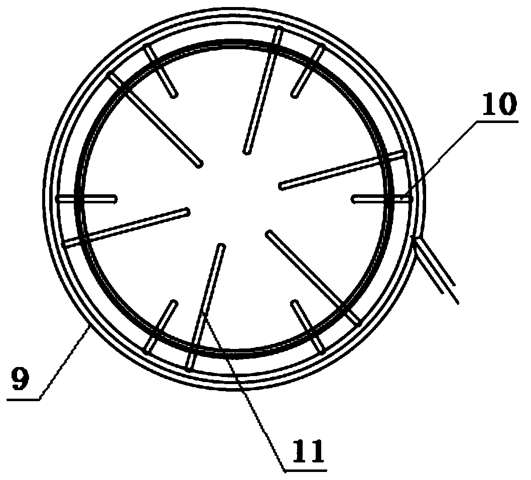
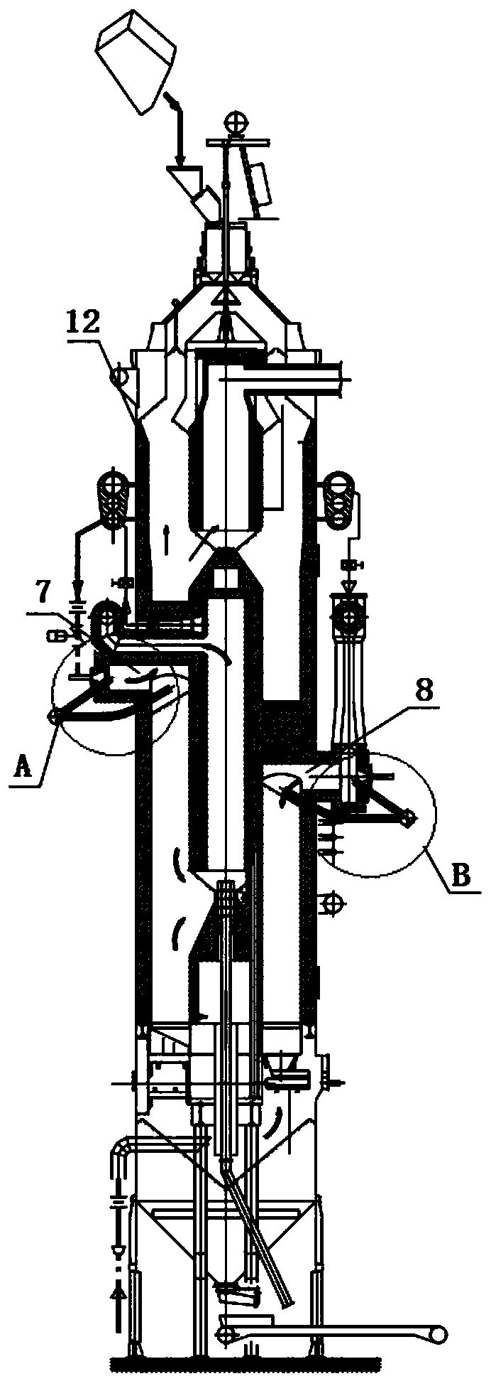
The invention discloses a sleeve kiln local oxygenation system. The sleeve kiln local oxygenation system comprises an oxygen generation unit, an ejection unit, a heat exchange unit and an oxygenationunit, wherein the oxygen generation unit is used for producing pure oxygen, the inlet end of the ejection unit is connected with the oxygen generation unit, the inlet end of the heat exchange unit isconnected with the outlet end of the ejection unit, the heat exchange unit is arranged on a hot gas pipeline from an upper inner sleeve outlet flue of the sleeve kiln to the heat exchanger, the inletend of the oxygenation unit is connected with the outlet end of the heat exchange unit, the oxygenation unit is arranged outside a combustion chamber, the oxygenation unit comprises an oxygenation annular pipe, a plurality of oxygenation spray guns and a plurality of oxygenation spray pipes are arranged on the oxygenation annular pipe in the circumferential direction, the oxygenation spray guns are arranged on a combustion chamber panel, and the oxygenation spray pipes are arranged below an arch bridge. According to the sleeve kiln local oxygenation system, after local oxygen-enriched combustion, the combustion efficiency is improved, the combustion-supporting air volume and the use amount of fuel can be properly reduced, a better energy-saving effect can be achieved, the ignition temperature of the fuel in an oxygen-enriched state can be reduced, the combustion speed is increased, the combustion process is violent, the combustion reaction is sufficient and complete, and a better heatexchange effect is achieved.

Description

technical field [0001] The invention relates to the technical field of sleeve kilns, in particular to a local oxygenation system for sleeve kilns. Background technique [0002] Annular sleeve kiln is widely used in lime production enterprises in the fields of metallurgy, chemical industry and building materials, and has become a highly concerned lime calcination technology. When the calorific value of the fuel is low, the burning intensity of the fuel in the kiln is insufficient, and the quicklime will not burn through. The low calorific value of the gas results in a small proportion of combustible components and a large proportion of useless gases. Under these conditions, the gas input volume and the combustion air volume are both high, and the calcining zone tends to extend to the kiln top preheating zone and the kiln bottom cooling zone. The large amount of dust affects the continuous and stable operation of the sleeve kiln and the control of equipment operating costs. ...

Claims


Application Information

Patent Timeline
Patent Type & Authority Applications(China)
IPC IPC(8): F27D7/02F27D17/00
CPCF27D7/02F27D17/004
Inventor 张林进赵波庞焕军唐丹满毅冀瑞峰
Owner JIANGSU ZHONGSHENGYUAN TECH CO LTD
Why Eureka
Eureka Blog
Learn More