
An inspection device

An inspection device and vibration detection technology, which is applied in the direction of measuring devices, testing of machine/structural components, testing of mechanical components, etc., can solve problems such as inspection lengthening

Active Publication Date: 2020-07-21
JATCO LTD
View PDF13 Cites 0 Cited by
  • Summary
  • Abstract
  • Description
  • Claims
  • Application Information

AI Technical Summary

Problems solved by technology

In this way, the inspection performed on the finished product of the automatic transmission becomes longer

Method used


Image

  • An inspection device
  • An inspection device
  • An inspection device

Examples


Embodiment Construction

[0059] Embodiments of the present invention will be described below.

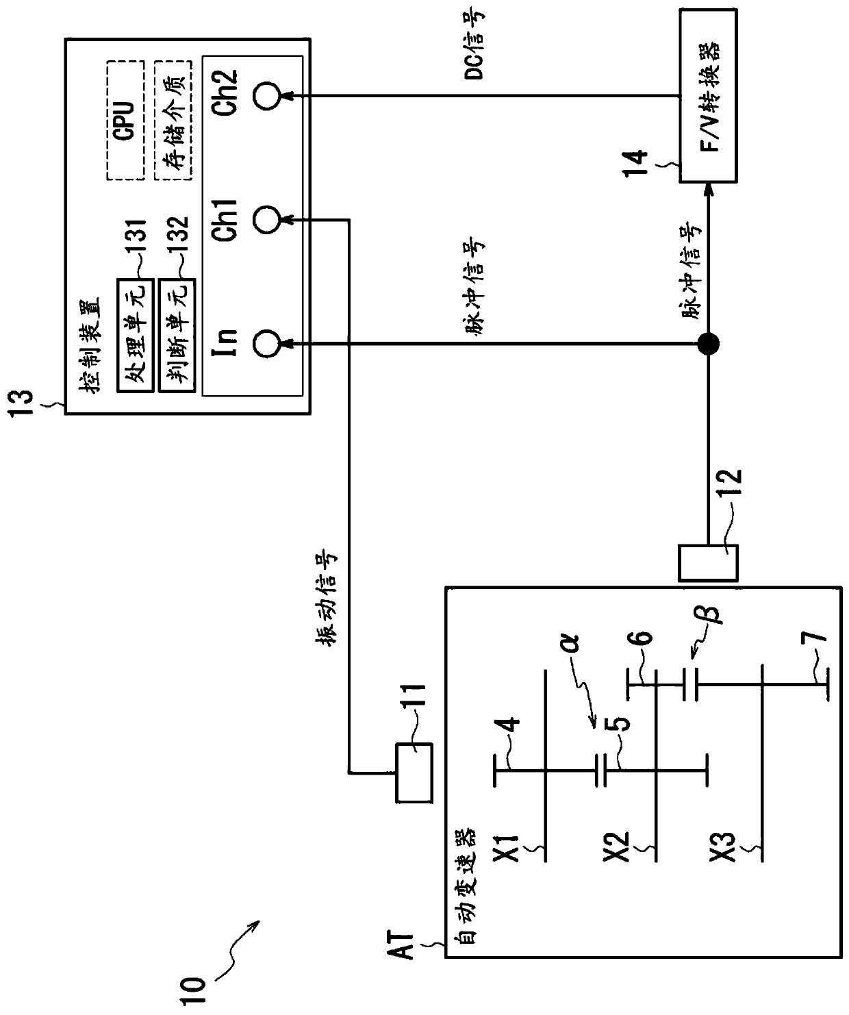
[0060] figure 1 It is a figure which shows the schematic structure of the inspection apparatus 10 of this embodiment.

[0061] The inspection device 10 includes a vibration sensor 11, a rotation sensor 12, a control device 13, and an F / V converter 14 (period / voltage converter).

[0062] The object to be inspected by the inspection device 10 is the automatic transmission AT for a vehicle. In the vehicular automatic transmission AT, a plurality of gear sets α, β are provided on a rotational driving force transmission path.

[0063] The inspection device 10 is provided for inspecting the presence or absence of defects in the gear members 4, 5, 6, 7 constituting the gear sets α, β.

[0064] The process of manufacturing a gear part includes a step of grinding the surface of a tooth part that is a meshing surface with another gear part. The purpose of this process is: (a) to remove the surface of the raw mate...


PUM


Abstract

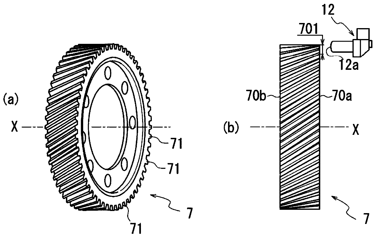
The invention provides an inspection device which can inspect the condition of excessive grinding in a shorter time. The inspection device (10) is provided with a vibration sensor (11) for detecting the vibration of the automatic transmission, and a control device (13). The control device functions as a processing means (131) for performing a synchronous averaging process on the vibration signal output by the vibration sensor, and as a determination means (132) for determining the presence or absence of an abnormality in gear members (4, 5, 6, 7) in the automatic transmission on the basis of the result of the synchronous averaging process. The inspection device includes a rotation sensor disposed to face a side surface of a region of an outer periphery of a gear member in which a tooth portion is provided, and an F / V converter that converts a pulse signal output by the rotation sensor into a voltage signal. In the control device, a processing means executes a synchronous averaging process of the voltage signal converted by the F / V converter, and a determination means determines whether or not there is an abnormality in the side surface shape of the tooth portion as viewed from therotation sensor side on the basis of the result of the synchronous averaging process of the voltage signal.

Description

technical field [0001] The present invention relates to an inspection device used in inspection of finished products of automatic transmissions for vehicles Background technique [0002] The automatic transmission for a vehicle is provided with a plurality of gear sets on a transmission path of rotational driving force. In each gear set, rotation is transmitted via intermeshing gear components. [0003] As an example, a gear part is made in the following steps. [0004] (1) A large-diameter portion is molded at an intermediate position in the longitudinal direction of the shaft portion by hot forging of a rod-shaped material. (2) A tooth portion is formed on the outer periphery of the large-diameter portion by cutting. (3) A carburizing treatment is performed on the gear member on which the teeth are formed. (4) Grinding the surface of the tooth part which will be the meshing surface with another gear part in the carburized gear part. [0005] Grinding of the teeth is c...

Claims


Application Information

Patent Timeline
Patent Type & Authority Applications(China)
IPC IPC(8): G01M13/028
CPCG01M13/028
Inventor 下坂俊郎
Owner JATCO LTD
Learn More