
Flue structure for SNCR (selective non-catalytic reduction) denitration of flue gas of pulverized coal boiler and heating of sludge drying heat-conducting oil

A technology for sludge drying and pulverized coal boilers, which is used in dewatering/drying/concentrating sludge treatment, heat storage heaters, fluid heaters, etc. The problems of high cost and high construction cost can achieve the effect of simplifying the heat transfer oil heating system, improving economic and social benefits, and reducing the concentration of NOx.

Pending Publication Date: 2020-07-17
HUANENG POWER INT INC +2
View PDF0 Cites 3 Cited by
  • Summary
  • Abstract
  • Description
  • Claims
  • Application Information

AI Technical Summary

Problems solved by technology

[0004] The purpose of the present invention is to provide a flue structure for SNCR denitrification of flue gas of pulverized coal boilers and heating sludge to dry heat transfer oil, which solves the problems of high construction cost and high cost of catalyst use in the flue gas denitration of existing pulverized coal boilers , as well as the complex structure of the dry municipal sludge heat exchanger that exists when coal-fired units are coupled to combust biomass

Method used


Image

  • Flue structure for SNCR (selective non-catalytic reduction) denitration of flue gas of pulverized coal boiler and heating of sludge drying heat-conducting oil
  • Flue structure for SNCR (selective non-catalytic reduction) denitration of flue gas of pulverized coal boiler and heating of sludge drying heat-conducting oil
  • Flue structure for SNCR (selective non-catalytic reduction) denitration of flue gas of pulverized coal boiler and heating of sludge drying heat-conducting oil

Examples


Embodiment Construction

[0023] The present invention will be described in further detail below in conjunction with the accompanying drawings.

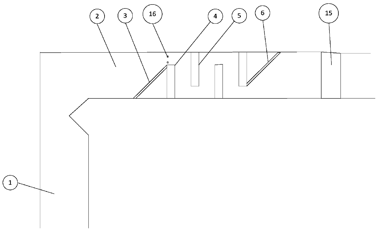
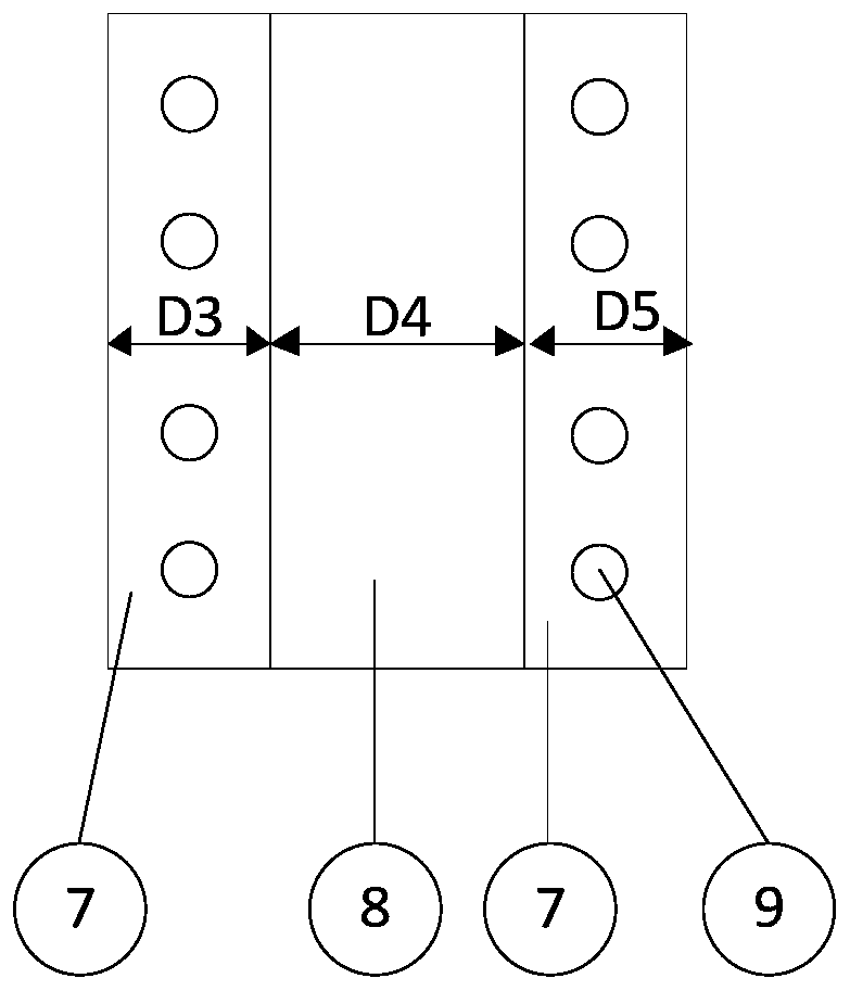
[0024] Such as Figure 1 to Figure 5 As shown, the present invention provides a flue structure for pulverized coal boiler flue gas SNCR denitration and heating sludge drying heat transfer oil, including pulverized coal boiler 1, flue 2, first inclined baffle plate 3, first Baffle 4, second baffle 5, second inclined baffle 6, refractory and wear-resistant material 7, heat-resistant steel plate structure 8, heat transfer oil heater pipe 9, control valve 10, heat transfer oil inlet header 11, heat conduction Oil outlet header 12, circulating pump 13, sludge dryer 14, SCR device 15 and spray gun 16, wherein the flue gas outlet of pulverized coal boiler 1 is connected to flue 2, and the flue gas outlet of said flue 2 is connected to There is a flue gas inlet for the SCR device 15 .

[0025] In the inner cavity of the flue 2, a first inclined baffle 3, a pluralit...


PUM


Abstract

The invention provides a flue structure for SNCR (selective non-catalytic reduction) denitration of flue gas of a pulverized coal boiler and heating of sludge drying heat-conducting oil. An SNCR denitration device is arranged in a proper area in a flue of the pulverized coal boiler, so that the flue gas carrying a reducing agent can be fully mixed when flowing through the SNCR denitration device,and ideal denitration efficiency is achieved. A heat-conducting oil heater pipeline is embedded in a basic mechanism unit, so that a heat-conducting oil heating system is simplified, and part of heatenergy in high-temperature flue gas is obtained for drying of municipal sludge. The whole design structure is simple, the concentration of NOx in the flue gas in front of an SCR device is greatly reduced, energy in the flue gas is obtained with the simple structure for drying of the municipal sludge, and better economic benefits and social benefits can be obtained in two aspects of pollutant emission reduction and municipal waste utilization.

Description

technical field [0001] The invention relates to the field of coal-fired boiler environmental protection technology and waste harmless treatment, in particular to a flue structure for SNCR denitrification of flue gas of pulverized coal boiler and heating sludge drying heat transfer oil. Background technique [0002] In order to meet the national requirements for ultra-low emission of pollutants (such as NOx, etc.) in flue gas emitted by coal-fired units, pulverized coal boilers generally use the selective catalytic reduction (SCR) method for NOx removal. This method has the disadvantages of high construction costs for denitrification devices, There are many problems such as high catalyst consumption, catalyst failure or poisoning, high disposal cost of spent catalyst and great potential harm to the environment. If most of the NOx can be removed before the flue gas enters the SCR device, the denitrification pressure of the downstream SCR device can be effectively relieved, whi...

Claims


Application Information

Patent Timeline
Patent Type & Authority Applications(China)
IPC IPC(8): F23J15/04F23J15/06F24H7/00B01D53/56B01D53/79C02F11/13
CPCF23J15/04F23J15/06F24H7/00B01D53/79B01D53/56C02F11/13F23J2215/10B01D2258/0283Y02E20/30
Inventor 林伟荣李昱喆宋润王海涛时正海高洪培苏林
Owner HUANENG POWER INT INC
Learn More