
Board turnover device

A technology for turning over devices and plates, applied in the directions of transportation and packaging, conveyor objects, etc., can solve the problems of increasing production costs, time-consuming and labor-intensive, unfavorable continuous production, etc., and achieve the effect of improving production efficiency and saving costs.

Pending Publication Date: 2020-07-17
GUANGDONG UNIV OF TECH
View PDF0 Cites 2 Cited by
  • Summary
  • Abstract
  • Description
  • Claims
  • Application Information

AI Technical Summary

Problems solved by technology

In the general production line, manual turning is used, which is time-consuming and labor-intensive, which increases production costs and is not conducive to continuous production.
On the automatic production line, the existing cage-type turning mechanism brings difficulties to later maintenance and repair due to its complex structure and bulky volume.

Method used


Image

  • Board turnover device
  • Board turnover device
  • Board turnover device

Examples


Embodiment 1

[0051] Embodiment 1 (flip 90 degrees):

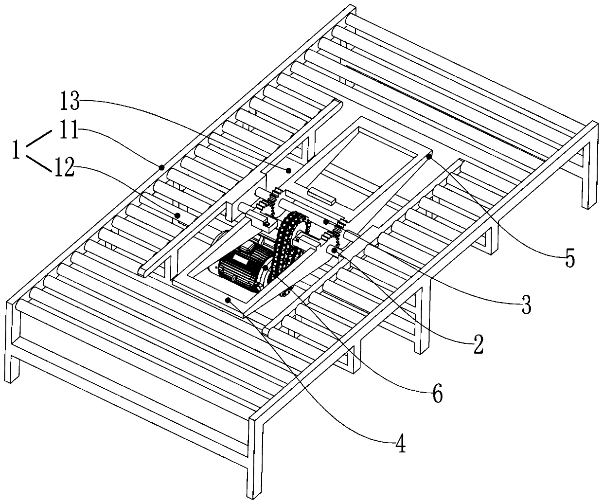
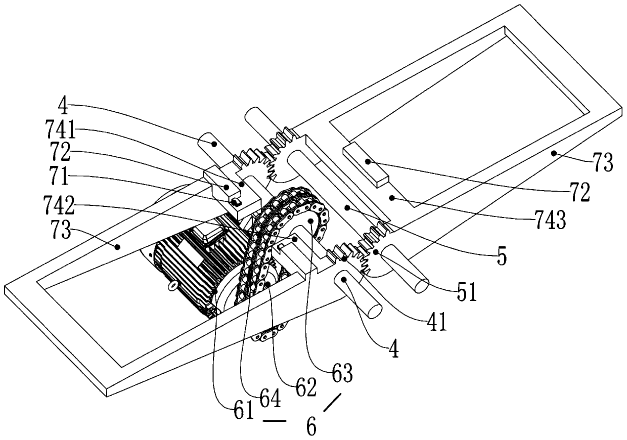
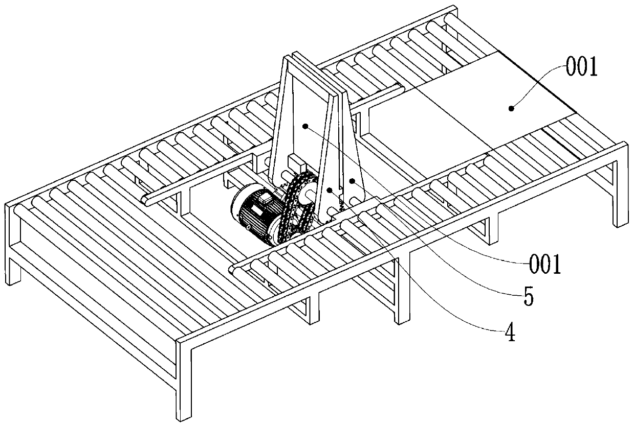
[0052] Such as Figure 5 , in the initial state, the plate is sent to the active turning part 4 (it can also be the driven turning part 5); as shown in the figure, the line between the active turning part 4 and the driven turning part 5 is the central axis 01; by controlling the driving gear 41 Consistent with the physical parameters of the driven gear 51 (such as physical parameters such as size, tooth structure size, tooth structure number, etc.), to adjust the active turning member 4 and the driven turning member 5 to reach the central axis 01 at the same time; start the turning drive assembly 6. Make the output end of the overturning drive assembly 6 rotate clockwise, since the active overturning part 4 and the driven overturning part 5 reach the central axis 01 at the same time, as Figure 6 , the active turning part 4 and the driven turning part 5 clamp the plate, realizing the effect of turning the plate 90 degrees, and the front ...

Embodiment 2

[0053] Embodiment 2 (flip 180 degrees):

[0054] Such as Figure 5 , in the initial state, the plate is sent to the active turning part 4 (also can be the driven turning part 5); the line between the active turning part 4 and the driven turning part 5 is the central axis 01; by controlling the driving gear 41 and the driven The physical parameters of the gear 51 are different (such as physical parameters such as size, toothed structure size, toothed structure number), so as to adjust the active turning part 4 to reach the central axis 01 at first; The output end rotates clockwise, driving the active turning part 4 to turn clockwise, and the driven turning part 5 to turn counterclockwise, such as Figure 7 , because the driving active turning part 4 first passes through the central axis 01 and exceeds the central axis 01, the driving active turning part 4 presses the plate to the driven turning part 5, and the active turning part 4 and the driven turning part 5 clamp the plate...


PUM


Abstract

The invention relates to a board turnover device which comprises a mounting frame, a turnover main shaft, a turnover auxiliary shaft, a driving turnover piece, a driven turnover piece and a turnover driving assembly. The turnover main shaft and the turnover auxiliary shaft are rotationally mounted on the mounting frame, the driving turnover piece is provided with a driving gear, and the driving gear is coaxially connected with the turnover main shaft; the driven turnover piece is provided with a driven gear, the driven gear is coaxially connected with the turnover auxiliary shaft, and the driving gear is meshed with the driven gear; the output end of the turnover driving assembly is connected with the turnover main shaft and used for driving the turnover main shaft to rotate, so that the driving turnover piece and the driven turnover piece rotate oppositely to be close to each other and rotate reversely to be away from each other; and the board turnover device is used for turning overwood boards, and the driving turnover piece and the driven turnover piece can be turned over under the driving action of the turnover driving assembly, so that the wood boards are turned over. The board turnover device is simple and compact, full-automatic turnover is achieved, the wood board turnover device can be applied to a common production line and a full-automatic production line, cost is effectively saved, and production efficiency is improved.

Description

technical field [0001] The invention relates to the technical field of sheet material conveyance, in particular to a sheet material turning device. Background technique [0002] In the board processing industry, especially when processing boards such as wood boards, metal boards, and plastic boards, it is necessary to perform deep processing such as sawing and polishing on the boards. During processing, it is often necessary to process both the front and back sides of the plate, which requires turning the plate 180 degrees before processing its other side. On the general production line, manual turning is used, which is time-consuming and labor-intensive, increases production costs, and is not conducive to continuous production. On the automatic production line, the existing cage-type turning mechanism brings difficulties to later maintenance and repair because of its complex structure and bulky volume. Contents of the invention [0003] The object of the present inventi...

Claims


Application Information

Patent Timeline
IPC IPC(8): B65G47/248
CPCB65G47/248
Inventor 赖苑鹏刘强赵荣丽张定王智杰严都喜
Owner GUANGDONG UNIV OF TECH
Learn More