Fastening clamp for battery module laser welding
A laser welding and battery module technology, applied in the direction of laser welding equipment, welding equipment, welding equipment, etc., can solve the problems that the welding position deviates from the predetermined position, the position of the battery is not fixed, and the welding yield is low, so as to achieve fast position fixing Stepping up, the overall structure design is scientific, and the effect of improving production efficiency
- Summary
- Abstract
- Description
- Claims
- Application Information
AI Technical Summary
Problems solved by technology
Method used
Image
Examples
specific Embodiment 1
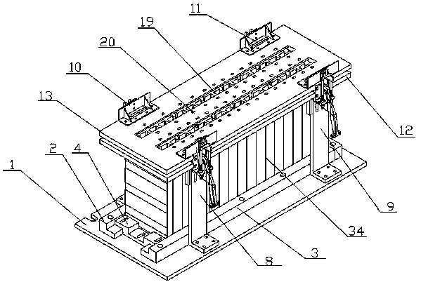
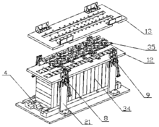
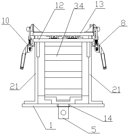
[0028] Specific embodiment 1: The core of the present invention is to provide a fastening fixture for laser welding of battery modules, aiming at the unfixed position of the battery existing in the welding of the battery module, prone to weak welding and deviation of the welding position from the predetermined position , low welding efficiency and low welding yield, a targeted design of the fixture suitable for battery module welding, which can tighten and fix the battery very accurately, in order to make people in the technical field better understand The technical solution of the present invention will be further described in detail below in conjunction with the accompanying drawings and specific embodiments of the present invention. It should be noted that when an element is referred to as "fixed" or "set to" another element, it can be directly or indirectly on another component. When an element is referred to as being "connected to" another element, it can be directly or i...
specific Embodiment 2
[0029] Specific embodiment 2: as specification attached Figure 7 As shown, in order to make the present invention have a more prominent and excellent use effect during use, on the basis of the above-mentioned specific embodiment 1, the present invention provides a ball for installing the ball 30 on the left support slide 2 and the right support slide 3. The ball installation groove 29 of the ball installation groove 29 is installed with a ball 30 for the sliding of the battery installation slide seat 4. Specifically, when the ball installation groove 29 on the left support slide seat 2 and the right support slide seat 3 After the ball 30 is installed, the lower part of the battery installation slide 4 is installed on the left support slide 2 and the right support slide 3 and contacts with the ball 30 on it, which greatly improves the battery installation slide 4 on the left support slide. Slide flexibility on seat 2 and right support slide seat 3.
specific Embodiment 3
[0030] Specific embodiment 3: as specification attached Figure 11 and manual attached Figure 12 As shown, in order to make the present invention have more prominent and excellent use effects during use, on the basis of the above-mentioned specific embodiment 1, a threaded through hole is opened on the L-shaped support plate 21, and in the threaded through hole Adjusting bolts 31 are set, and a clamping plate 32 for tightening the battery pack 34 is installed on the inner end of the adjusting bolt 31. A guide sleeve 33 is fixedly installed on the clamping plate 32, and the inner end of the adjusting bolt 31 is installed on the guide sleeve. 33 and can rotate in the guide sleeve 33, specifically, in the specific use process, the adjusting bolt 31 will push the clamping plate 32 to the battery pack 34 while rotating in the threaded through hole provided on the L-shaped support plate 21. The direction of the side wall of the battery pack 34 is moved, and then the side wall of t...
PUM
 Abstract
Description
Claims
Application Information
 - R&D
- Intellectual Property
- Life Sciences
- Materials
- Tech Scout
- Unparalleled Data Quality
- Higher Quality Content
- 60% Fewer Hallucinations
Browse by: Latest US Patents, China's latest patents, Technical Efficacy Thesaurus, Application Domain, Technology Topic, Popular Technical Reports.
© 2025 PatSnap. All rights reserved.Legal|Privacy policy|Modern Slavery Act Transparency Statement|Sitemap|About US| Contact US: help@patsnap.com


