A kind of manufacturing method of mems structure

A manufacturing method and vibration direction technology, applied in the direction of sensors, electrostatic transducers, microphones, electrical components, etc., can solve the problems that restrict the development of MEMS piezoelectric microphones, low sensitivity of piezoelectric MEMS structures, and easy warping of diaphragms, etc. Achieve the effects of reducing process difficulty, improving performance and improving sensitivity

Active Publication Date: 2021-04-06
ANHUI ORINFIN ACOUSTIC SCI&TECH CO LTD
View PDF8 Cites 0 Cited by
  • Summary
  • Abstract
  • Description
  • Claims
  • Application Information

AI Technical Summary

Problems solved by technology

At the same time, compared with condenser microphones, there are advantages such as no need for bias voltage, wide operating temperature range, dustproof, waterproof, etc., but its sensitivity is relatively low, which restricts the development of MEMS piezoelectric microphones.
Moreover, when the diaphragm size of the MEMS piezoelectric microphone is large, it is easy to cause the diaphragm to warp
[0003] For the problems of how to improve the low sensitivity of the piezoelectric MEMS structure and the easy warping of the diaphragm in related technologies, no effective solution has been proposed so far.

Method used


Image

  • A kind of manufacturing method of mems structure
  • A kind of manufacturing method of mems structure
  • A kind of manufacturing method of mems structure

Examples


Embodiment Construction

[0031] The following will clearly and completely describe the technical solutions in the embodiments of the application with reference to the drawings in the embodiments of the application. Apparently, the described embodiments are only some of the embodiments of the application, not all of them. All other embodiments obtained by persons of ordinary skill in the art based on the embodiments in this application belong to the protection scope of this application.

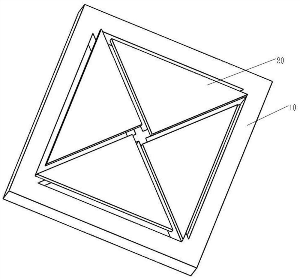
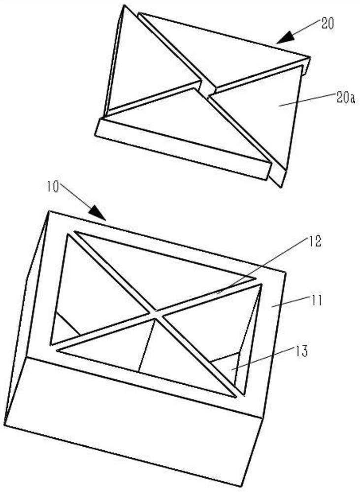
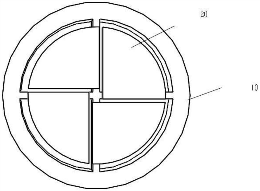
[0032] see figure 1 , according to an embodiment of the present application, a MEMS structure is provided, which can be but not limited to be used in sensors such as microphones or microphones, or other actuators. In some embodiments, the MEMS structure includes a substrate 10 and a piezoelectric composite vibration layer 20 .

[0033] see figure 2 , the substrate 10 includes an outer ring body 11 and a support plate 12 disposed inside the outer ring body 11 and connected to the outer ring body 11 , wherein a cavit...


PUM


Abstract

The present application discloses a method for manufacturing a MEMS structure, comprising: forming a piezoelectric composite vibration layer on the front surface of a substrate; etching the back surface of the substrate until reaching the piezoelectric composite vibration layer, so that the substrate includes an outer ring body and a support plate arranged in the outer ring body and connected to the outer ring body, wherein a cavity is formed between the support plate and the outer ring body; the piezoelectric composite vibration layer is divided by etching , the piezoelectric composite vibration layer includes a fixed end connected to the support plate and a free end suspended above the cavity. The manufacturing method of the MEMS structure provided by the application reduces the process difficulty and improves the performance of the MEMS structure.

Description

technical field [0001] The present application relates to the field of semiconductor technology, and in particular, to a method for manufacturing a MEMS (abbreviation for MicroelectroMechanical Systems, microelectromechanical systems) structure. Background technique [0002] MEMS microphones (microphones) mainly include two types: capacitive and piezoelectric. MEMS piezoelectric microphone is a microphone prepared by microelectromechanical system technology and piezoelectric thin film technology. Due to the use of semiconductor planar technology and bulk silicon processing technology, it has small size, small volume and good consistency. At the same time, compared with condenser microphones, there are advantages such as no need for bias voltage, wide operating temperature range, dustproof, waterproof, etc., but its sensitivity is relatively low, which restricts the development of MEMS piezoelectric microphones. Moreover, when the diaphragm size of the MEMS piezoelectric mic...

Claims


Application Information

Patent Timeline
Patent Type & Authority Patents(China)
IPC IPC(8): H04R19/00H04R19/04H04R31/00
CPCH04R19/005H04R19/04H04R31/00
Inventor 刘端
Owner ANHUI ORINFIN ACOUSTIC SCI&TECH CO LTD
Why Eureka
Try Eureka