Reed type vacuum contact mechanism

A contact mechanism and reed type technology, applied in the direction of detailed information of electromagnetic relays, relays, electrical components, etc., can solve problems such as inconvenient opening and closing conduction operations, achieve safe and reliable layout and planning, reduce processing costs, Ease of maintenance and repair

Pending Publication Date: 2020-07-14
SHENZHEN DACHENG PRECISION EQUIP CO LTD
View PDF0 Cites 0 Cited by
  • Summary
  • Abstract
  • Description
  • Claims
  • Application Information

AI Technical Summary

Problems solved by technology

[0004] Therefore, the embodiment of the present invention provides a reed type vacuum contact mechanism to solve the problem that the two contacts of the electromagnetic relay in the prior art are inconvenient to open and close.

Method used


Image

  • Reed type vacuum contact mechanism
  • Reed type vacuum contact mechanism
  • Reed type vacuum contact mechanism

Examples


Embodiment 1

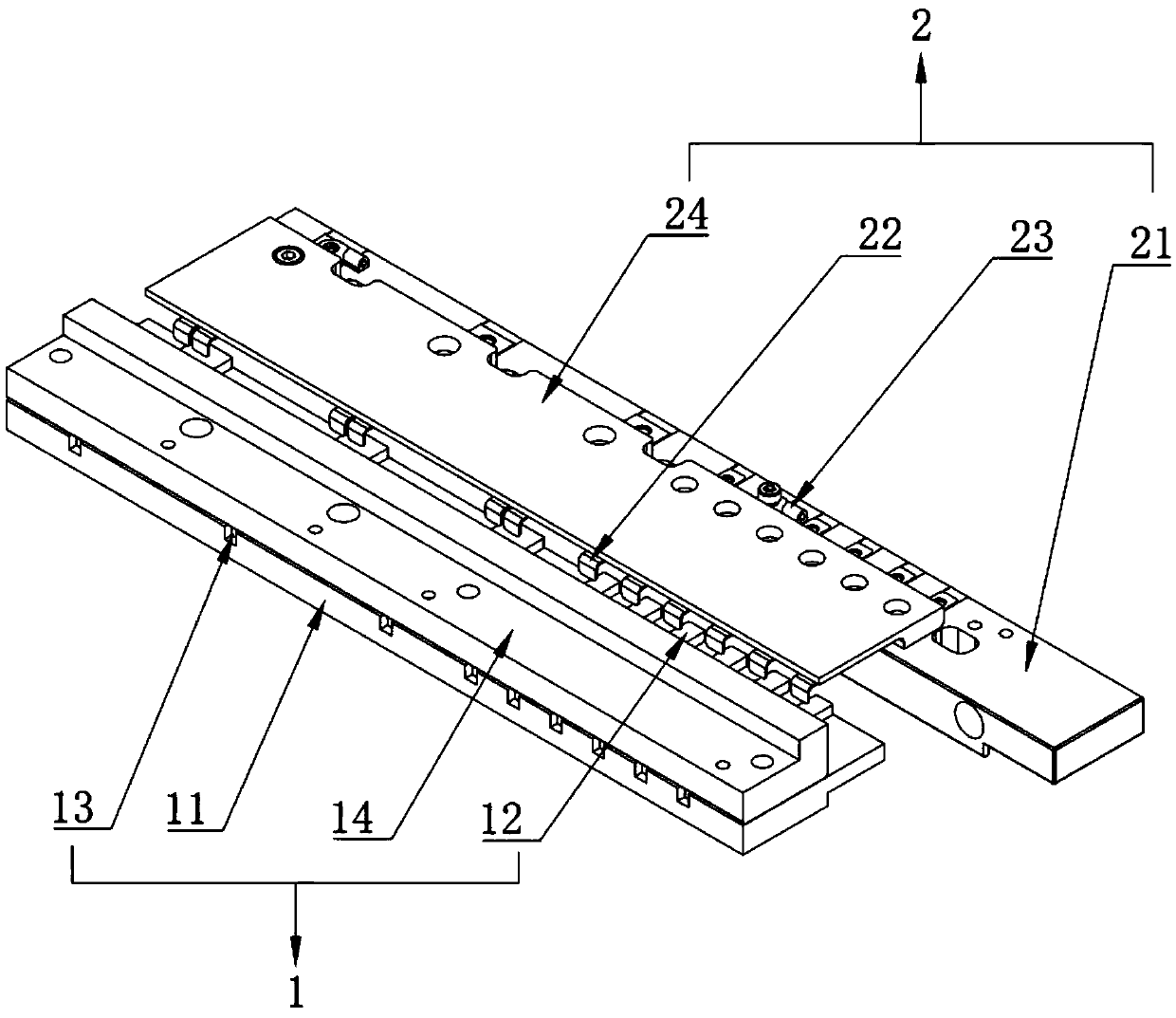
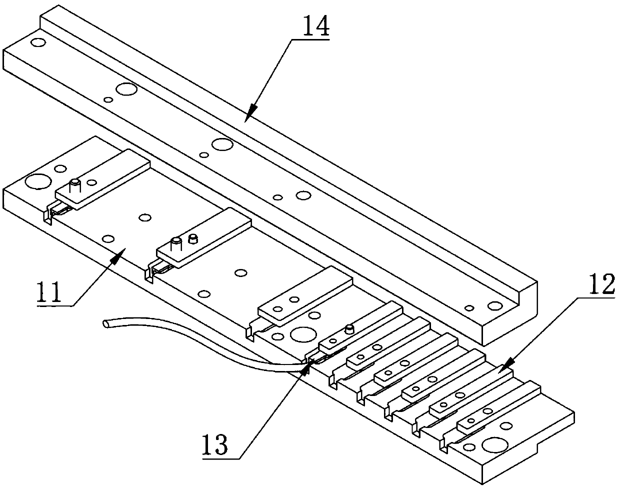
[0031] Such as figure 1 As shown, the embodiment of the present invention provides a reed type vacuum contact mechanism, which includes a static contact group 1 and a movable contact group 2 which are oppositely arranged. Static contact group 1 comprises the static contact mounting plate 11 that is installed on the horizontal moving equipment and is installed on the multiple static contact 12 on the static contact mounting plate 11 upper surface, and multiple static contact 12 along the static contact The mounting plate 11 is distributed along the length direction, and a plurality of static contacts 12 are all bolted to the static contact mounting plate 11 . The first copper lug 13 (referring to figure 2 ), and the first copper nose 13 is bolted to the static contact 12, and a static contact cover 14 for covering the non-contact end of the static contact 12 is provided above the first copper nose 13, thereby preventing the static contact 12 from contacting the wire The join...

Embodiment 2

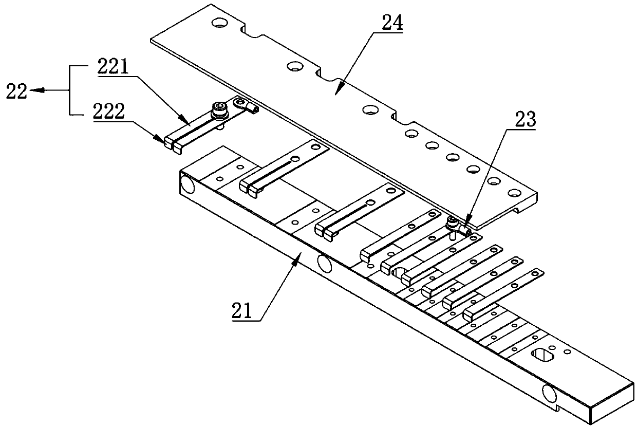
[0035] The difference from Example 1 is that the combination figure 1 and Figure 4 shown. On the bottom surface of the movable contact mounting plate 21 are etched a plurality of wire grooves 3 for fixing wires, and one end of the wire grooves 3 is provided with a threaded hole that runs through the moving contact mounting plate 21 and is used for wires to pass through 4. Make the wires connected to the movable contact 22 pass through the threaded hole 4 and insert them into the wire groove 3 from the bottom surface of the movable contact mounting plate 21, so that the arrangement and planning of the circuit are safe, reliable, clean and beautiful, and convenient for maintenance and overhaul.


PUM


Abstract

The embodiment of the invention discloses a reed type vacuum contact mechanism. The mechanism comprises a static contact group and a moving contact group which are oppositely arranged. The static contact group comprises a static contact mounting plate mounted on the horizontal moving equipment and a plurality of static contacts mounted on the upper surface of the static contact mounting plate; themovable contact group comprises a movable contact mounting plate mounted on the lifting mechanism and a plurality of movable contacts mounted on the upper surface of the movable contact mounting plate; the moving contact mounting plate is provided with a plurality of moving contacts, the moving contacts are distributed in the length direction of the moving contact mounting plate, each moving contact is a leaf spring of an L-shaped structure and comprises a horizontally-arranged mounting portion and a vertically-downwards-arranged conduction portion, and the conduction portions are integrallyformed at the ends, away from the moving contact mounting plate, of the mounting portions and used for making contact with the static contacts. According to the embodiment of the invention, reed typemoving contact contact is utilized, so the static contact group and the moving contact group realize relative movement in the horizontal direction, the contact mechanism realizes stable contact conduction under vacuum, and the vacuum circuit breaker is simple in structure and low in processing cost.

Description

technical field [0001] Embodiments of the present invention relate to the technical field of contact mechanisms, in particular to a reed type vacuum contact mechanism. Background technique [0002] In general, an electromagnetic contactor is a type of circuit switching device that uses electromagnetic principles to perform mechanical transmission and send current signals. Electromagnetic contactors are installed in various types of industrial equipment, machines, vehicles, etc., and the electromagnetic contactor may include: a main contact mechanism for performing power supply to a load or cutting off power supply to a load; and an auxiliary contact mechanism, It is used to carry out the power supply to the solenoid coil of the main contact mechanism or to cut off the power supply to the solenoid coil of the main contact mechanism. [0003] In the prior art, the electromagnetic relay used in the vacuum state controls the rise and fall of a group of a pair of contacts, but t...

Claims


Application Information

Patent Timeline
Patent Type & Authority Applications(China)
IPC IPC(8): H01H50/54H01H50/56
CPCH01H50/54H01H50/56
Inventor 张孝平
Owner SHENZHEN DACHENG PRECISION EQUIP CO LTD
Why Eureka
Try Eureka