Boiler flue gas recovery heater

A technology of boiler flue gas and heater, which is applied in the field of boiler flue gas recovery heater and boiler flue gas recovery device. The effect of pressure

Inactive Publication Date: 2020-07-14
朱陆一
View PDF13 Cites 1 Cited by
  • Summary
  • Abstract
  • Description
  • Claims
  • Application Information

AI Technical Summary

Problems solved by technology

[0004] However, there is still a problem with the above-mentioned device: the flue gas contains a lot of dust, and the dust adheres to the inner wall of the flue pipe, which will hinder the heat transfer of the flue pipe. performance
The above-mentioned device can only be dismantled when cleaning the smoke pipe, which is inconvenient to operate

Method used


Image

  • Boiler flue gas recovery heater
  • Boiler flue gas recovery heater
  • Boiler flue gas recovery heater

Examples


Embodiment Construction

[0021] The following are specific embodiments of the present invention combined with the accompanying drawings to further describe the technical solutions of the present invention, but the present invention is not limited to these embodiments.

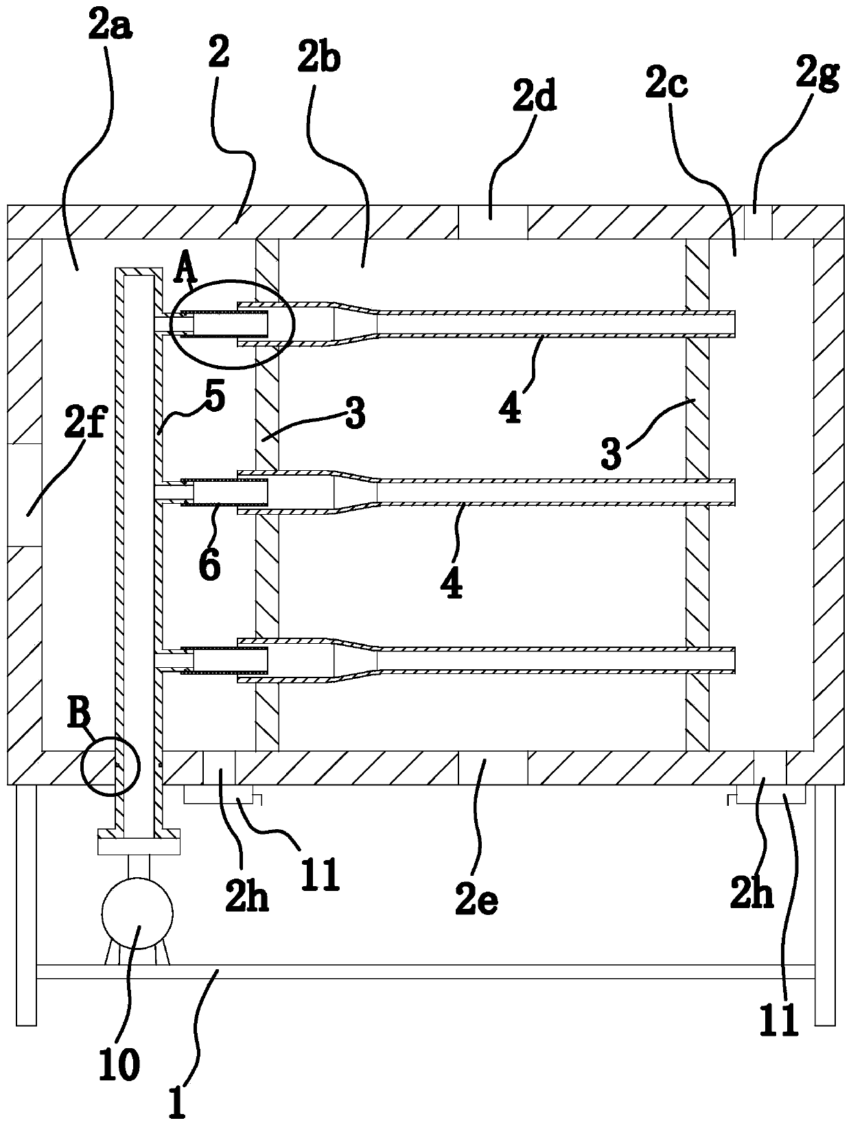
[0022] Such as figure 1 As shown, the boiler flue gas recovery heater includes a bracket 1 and a casing 2 fixed on the bracket 1. Two sealing plates 3 are vertically fixed in the casing 2. The two sealing plates 3 separate the inner cavity of the casing 2 into Cavity one 2a, cavity two 2b, and cavity three 2c are sequentially arranged from left to right, and cavity one 2a, cavity two 2b, and cavity three 2c are not connected to each other. Preferably, the sealing plate 3 is fixedly connected to the housing 2 by welding.

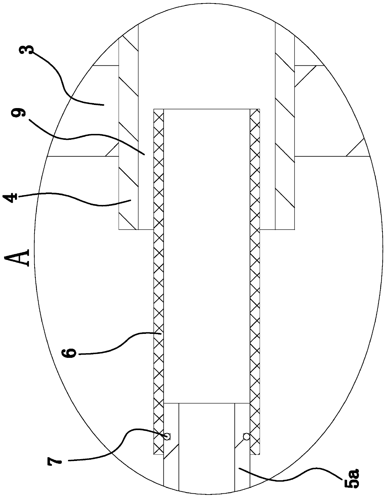
[0023] Wherein, the second cavity 2b is horizontally provided with a heat conduction pipe 4 made of heat conduction material. The material of the heat conduction pipe 4 can be brass or aluminum alloy. Preferably, the heat ...


PUM


Abstract

The invention provides a boiler flue gas recovery heater. The boiler flue gas recovery heater comprises a support and a shell fixed to the support. Two sealing plates are fixed in the shell. The two sealing plates partition an inner cavity of the shell into a first cavity, a second cavity and a third cavity in sequence from left to right. Heat conducting pipes are horizontally arranged in the second cavity. The two ends of the heat conducting pipes are located in the first cavity and the third cavity correspondingly. A water inlet pipe and water discharging pipes are fixed in the first cavity,the left ends of the water discharging pipes communicate with the water inlet pipe, and the right ends of the water discharging pipes are inserted into the left ends of the heat conducting pipes correspondingly. The left and right ends of the heat conducting pipes are each in the shape of a circular pipe, the middles of the heat conducting pipes are each in the shape of a circular cone, the maximum inner diameter and the minimum inner diameter of the middle of each heat conducting pipe are equal to the inner diameter of the left end and the inner diameter of the right end of each heat conducting pipe correspondingly, the outer diameter of each water discharging pipe is smaller than the inner diameter of the left end of each heating conducting pipe, and the inner diameter of each water discharging pipe is greater than the inner dimeter of the right end of each heat conducting pipe. The boiler flue gas recovery heater further comprises a water pump, an outlet of the water pump communicates with the water inlet pipe, and two water discharging outlets are formed in the bottom of the shell and communicate with the first cavity and the third cavity correspondingly. The boiler flue gas recovery heater provided by the invention has the advantage that the heat conducting pipes are convenient to clean.

Description

Technical field [0001] The invention belongs to the field of energy saving and environmental protection, and relates to a boiler flue gas recovery device, in particular to a boiler flue gas recovery heater. Background technique [0002] Existing boiler flue gas recovery devices, such as a gas-fired oil-fired boiler flue gas recovery energy saver disclosed by the Chinese Patent Library [application number: 200920310875.6; authorized announcement number: CN 201475978 U], are equipped with a gas-fired oil-fired boiler exhaust pipe connected The flue gas interface is connected to one end of a water tank with a volume of 0.25m3-3m3. There are 30-240 flue pipes placed in parallel with the flue gas interface in the water tank. The distance between the upper and lower pipes is 60- 100mm, the cold water inlet pipe and the hot water outlet pipe are arranged on the water tank shell, the smoke outlet pipe is arranged at the other end of the water tank, the sewage pipe is arranged at the bott...

Claims


Application Information

Patent Timeline
Patent Type & Authority Applications(China)
IPC IPC(8): F28D7/16F28G9/00
CPCF28D7/16F28G9/00
Inventor 不公告发明人
Owner 朱陆一
Why Eureka
Try Eureka