Thick Section Narrow Gap T-Type Welding Method
A welding method and narrow gap technology, applied in the direction of welding equipment, welding accessories, welding rod characteristics, etc., can solve the problems of difficult weld bead planning, irregular weld bead, and lack of fusion between passes, so as to simplify weld bead planning and reduce Welding volume, the effect of avoiding non-fusion between weld passes
- Summary
- Abstract
- Description
- Claims
- Application Information
AI Technical Summary
Problems solved by technology
Method used
Image
Examples
Embodiment 1
[0058] As a preferred embodiment of the present invention, this embodiment discloses:
[0059] Thick-section narrow-gap T-type welding method is characterized in that: comprising the following steps:
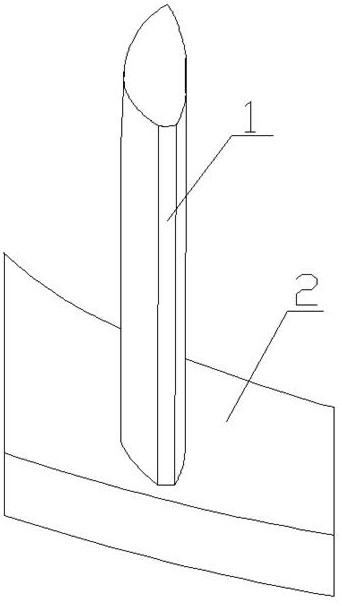
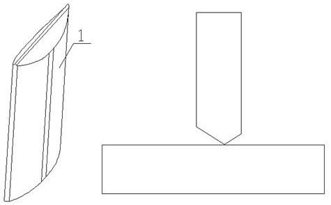
[0060] Groove design steps: process the special-shaped thick plate within 60mm above the welding end into a rectangular structure, the width of the rectangular structure is not less than the maximum width of the special-shaped thick plate 1; the welding surface of the rectangular structure is an oblique welding surface 4 with a certain slope , forming a Type I narrow gap groove structure, the gap between the root of the Type I narrow gap groove and the planar thick plate 2 is less than 16mm, and the gap between the upper end of the Type I narrow gap groove and the planar thick plate 2 is less than 20mm ; Open a conventional K-shaped bevel at both ends of the special-shaped thick plate 1 with a certain length, and leave a certain gap between the K-shaped bevel and the I-like narr...
Embodiment 2
[0067] As another preferred embodiment of the present invention, with reference to the attached Figure 1-6 , this example discloses:
[0068] Thick-section narrow-gap T-type welding method is characterized in that: comprising the following steps:
[0069] Groove design steps: process the special-shaped thick plate within 60mm above the welding end into a rectangular structure, the width of the rectangular structure is not less than the maximum width of the special-shaped thick plate 1; the welding surface of the rectangular structure is an oblique welding surface 4 with a certain slope , forming a Type I narrow gap groove structure, the gap between the root of the Type I narrow gap groove and the planar thick plate 2 is less than 16mm, and the gap between the upper end of the Type I narrow gap groove and the planar thick plate 2 is less than 20mm ; Open a conventional K-shaped bevel at both ends of the special-shaped thick plate 1 with a certain length, and leave a certain g...
Embodiment 3
[0076] As another preferred embodiment of the present invention, with reference to the attached Figure 1-11 , this example discloses:
[0077] The use of welding robots 113 is the direction of the future manufacturing industry. For robot welding of special-shaped structural thick plates and ultra-thick plates, it is necessary to improve the welding quality and efficiency of arc welding robots. Therefore, by changing the welding structure of the product, we change the welding groove of the thick plate and the ultra-thick plate, and carry the new welding technology on the arc welding robot to reduce the welding amount of the ultra-thick section structural parts, thereby increasing the welding efficiency of the arc welding robot , opened up a new field of intelligent welding of arc welding robots in the hydropower industry of power generation equipment.
[0078] Narrow gap gas shielded welding welding technology is a new type of welding technology, which mainly has the followi...
PUM
| Property | Measurement | Unit |
|---|---|---|
| length | aaaaa | aaaaa |
| thickness | aaaaa | aaaaa |
| thickness | aaaaa | aaaaa |
Abstract
Description
Claims
Application Information
 - R&D
- Intellectual Property
- Life Sciences
- Materials
- Tech Scout
- Unparalleled Data Quality
- Higher Quality Content
- 60% Fewer Hallucinations
Browse by: Latest US Patents, China's latest patents, Technical Efficacy Thesaurus, Application Domain, Technology Topic, Popular Technical Reports.
© 2025 PatSnap. All rights reserved.Legal|Privacy policy|Modern Slavery Act Transparency Statement|Sitemap|About US| Contact US: help@patsnap.com


