
Heat exchanger

A technology for heat exchangers and heat exchange parts, applied in heat exchange equipment, water heaters, air heaters, etc., can solve the problems of low flow, reduced heat exchange performance, noise generation, etc., to achieve production automation and simplify production process, the effect of improving heat transfer efficiency

Inactive Publication Date: 2020-07-10
KYUNGDONG NAVIEN
View PDF7 Cites 1 Cited by
  • Summary
  • Abstract
  • Description
  • Claims
  • Application Information

AI Technical Summary

Problems solved by technology

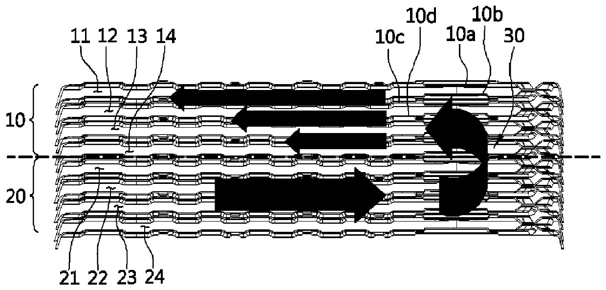
Therefore, in the heat medium flow path 11 formed by the outer peripheral plate 10a, a large flow rate of heat medium is supplied even though the amount of heat absorbed is small. The heat medium flow channels 12, 13, 14, although the heat of the combustion gas is transferred through the two plates 10c, 10d and absorbs a lot of heat, they still provide a small flow of heat medium, so that there is a gap between the heat medium flow and the absorption flow. imbalance
[0010] In this way, in the case where the flow path of the heat medium in the heat medium flow path of each layer and the absorbed heat transferred to the heat medium through the plate cannot be balanced, there is a problem that the heat exchange performance between the heat medium and the combustion gas Reduced, and in the area where the flow rate of the heat medium is small, due to local overheating, noise is generated by the boiling of the heat medium and foreign matter such as lime (Lime) is precipitated

Method used


Image

  • Heat exchanger
  • Heat exchanger
  • Heat exchanger

Examples


Embodiment Construction

[0072] Hereinafter, configurations and functions of preferred embodiments of the present invention will be described with reference to the drawings.

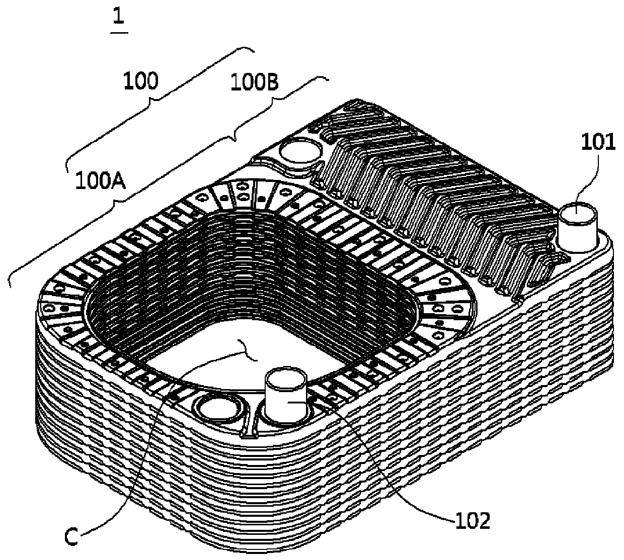
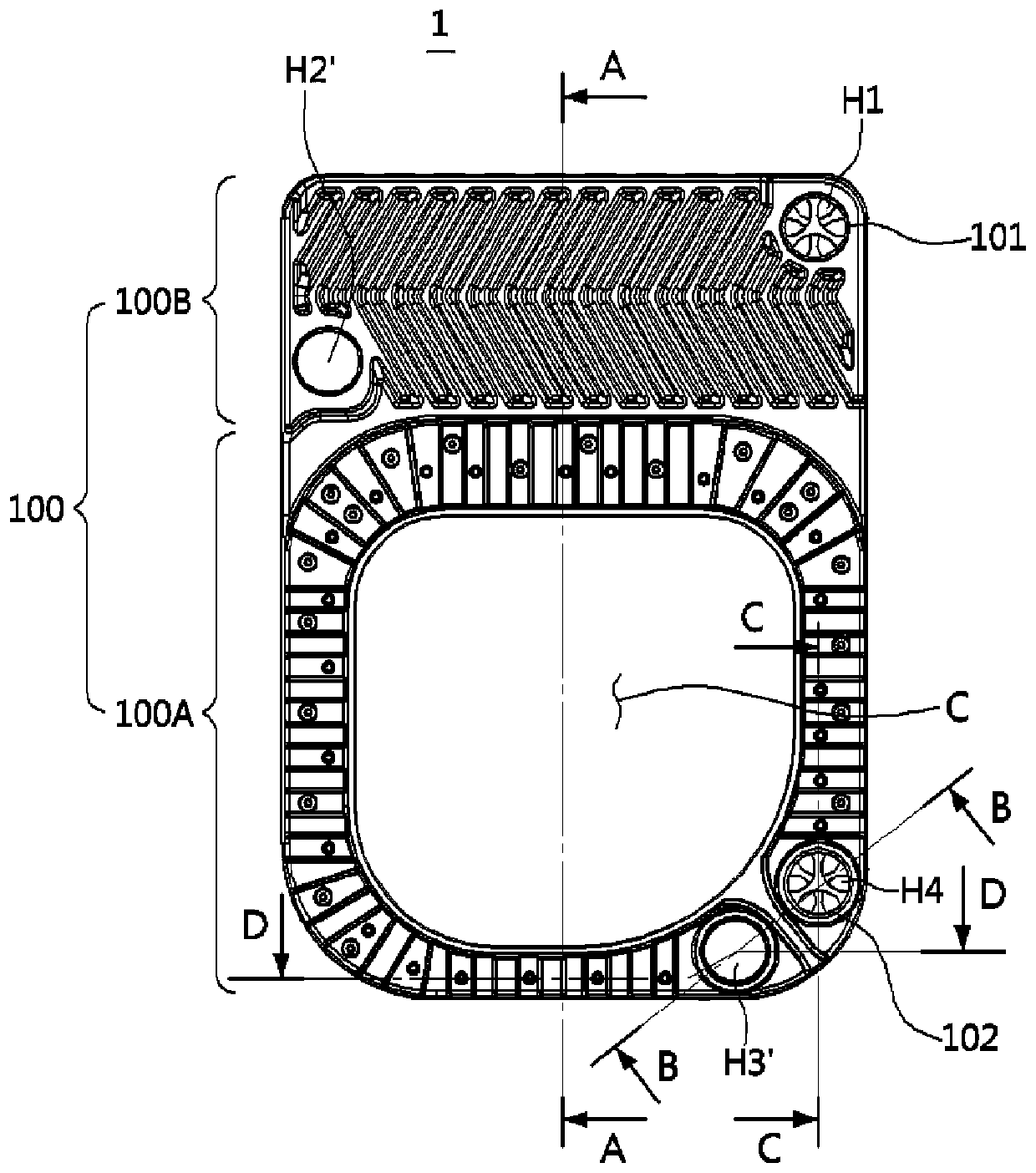
[0073] refer to Figure 2 to Figure 7 , the heat exchanger 1 according to an embodiment of the present invention is composed of a heat exchange part 100 formed by stacking a plurality of plates around the combustion chamber C, wherein the combustion chamber passes through the burner (not shown) Combustion produces combustion heat and combustion gas.

[0074] The heat exchange part 100 includes: a sensible heat exchange part 100A, which surrounds the outside of the combustion chamber C and is formed by one side region of the plate, and uses the sensible heat of the combustion gas generated by the combustion of the burner to heat the heat medium Heating; the latent heat exchange part 100B is formed by the other side region of the plate, and heats the heat medium by utilizing the latent heat generated when the water vapor containe...


PUM


Abstract

The purpose of the present invention is to provide a heat exchanger capable of suppressing boiling and lime precipitation due to local overheating of a heating medium and at the same time improving heat transmittance efficiency. The heat exchanger of the present invention for achieving said purpose comprises: heating medium flow paths, through which a heating medium flows, inside a plurality of laminated plates; and a heat exchange unit in which combustion gas flow paths, through which a combustion gas flows, are alternately formed to be adjacent to each other, wherein the heat exchange unitshave a heating medium differential distribution unit which enables the flow rate of the heating medium to be differentially distributed to parallel heating medium flow paths of the heat exchange unitsuch that the flow rate of the heating medium passing through the parallel heating medium flow paths is balanced with the quantity of absorbed heat transmitted to the plates.

Description

technical field [0001] The present invention relates to a heat exchanger, in particular to a method for distributing the flow difference of the heat medium so as to balance the flow and heat absorption of the heat medium passing through the heat medium flow path formed as a multi-layer between a plurality of plates , so as to suppress the boiling of the heat medium and the precipitation of lime, and at the same time, it can improve the heat transfer efficiency of the heat exchanger. Background technique [0002] A boiler for heating or hot water is a device that uses a heat source to heat heating water or direct supply water (hereinafter, collectively referred to as "heat medium") to heat or supply hot water to a desired area. A burner for burning a mixture of gas and air, and a heat exchanger for transferring the combustion heat of the combustion gas to a heat medium. [0003] As an example of the prior art related to heat exchangers, Korean Patent No. 10-0813807 discloses...

Claims


Application Information

Patent Timeline
Patent Type & Authority Applications(China)
IPC IPC(8): F28D1/03F28D9/00F28F9/02F28F19/00F24H8/00F28F9/22F28D21/00
CPCF24H8/00F28D9/0037F28D9/0056F28D20/021F28F19/00F28D2021/0024F28F9/026F28F3/086F28F13/08F28D9/0093Y02B30/00F28D1/0316F28D9/0031F28F9/0273F28F2009/222F24H1/0027F24H1/124F24H9/02F24H9/45F24H9/139
Inventor 郑仁喆朴埈吉
Owner KYUNGDONG NAVIEN
Learn More