
Test device for measuring axial multi-point slip amount of concrete-filled steel tube

A technology for concrete-filled steel tubes and test devices, which is applied in the field of civil engineering research, can solve the problems of not being able to reflect the sliding performance of concrete-filled steel tubes in detail, the difference in sliding deformation between the free end and the loading end, and the small gap between the steel tube and the core concrete, etc., to achieve Promote the effect of high application value, low manufacturing and processing difficulty, and fast testing speed

Pending Publication Date: 2020-07-10
TAIYUAN UNIV OF TECH
View PDF6 Cites 2 Cited by
  • Summary
  • Abstract
  • Description
  • Claims
  • Application Information

AI Technical Summary

Problems solved by technology

[0002] The concrete-filled steel tube structure has the advantages of high compressive strength and rapid construction, and has been gradually popularized and applied in long-span bridge structures. However, due to the shrinkage of the concrete or the influence of the construction process, there are gaps between the steel tube and the core concrete, and the bonding between the interfaces is slippery. The transfer effect significantly affects its mechanical properties
Aiming at the bond-slip performance of CFST, relevant scholars at home and abroad have carried out a large number of push-out tests of CFST. Some push-out tests only study the slip deformation at the loading end and the free end, and the average slip deformation is used as the slip constitutive relation. Slip amount, the disadvantage of this method is that there is a big difference between the slip deformation at the free end and the loading end, and taking the maximum or average value of slip as a parameter is not enough to finely reflect the slip performance of CFST
Some scholars also obtained slip deformation indirectly through numerical calculation by bonding resistance strain gauges on steel pipes, but this method has not been verified by actual measurement results, and its accuracy is open to question
Due to the small gap between the steel pipe and the core concrete in the poured concrete-filled steel pipe member, it is impossible to directly measure the sliding deformation by arranging displacement meters

Method used


Image

  • Test device for measuring axial multi-point slip amount of concrete-filled steel tube
  • Test device for measuring axial multi-point slip amount of concrete-filled steel tube
  • Test device for measuring axial multi-point slip amount of concrete-filled steel tube

Examples


Embodiment Construction

[0022] In order to have a clearer understanding of the technical features, purposes and effects of the present invention, the specific implementation manners of the present invention will now be described in detail with reference to the accompanying drawings.

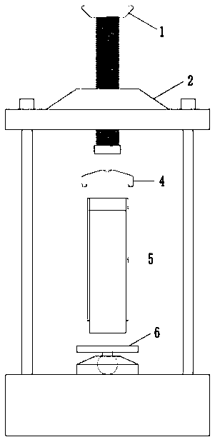
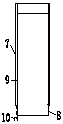
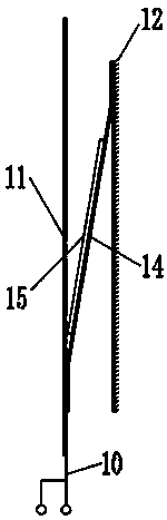
[0023] Such as Figure 1-4 As shown, the present invention provides a test device for measuring the axial multi-point slippage of concrete filled steel tubes, comprising a pressurized bolt 1, a workbench 2, an upper clamping groove 4, a concrete filled steel tube specimen 5 and a bottom platform 6; The cloud platform 6 is placed on the platform of the workbench 2, and the steel pipe concrete specimen 5 is placed between the upper slot 4 and the bottom platform 6, and an external load controlled by force or deformation is applied through the pressure bolt 1, so that The force or load applied to the concrete-filled steel pipe specimen 5 reaches a uniform force, and the push-out test load of the concrete-filled steel pipe ...


PUM

PropertyMeasurementUnit
widthaaaaaaaaaa

Abstract

The invention relates to a test device for measuring the axial multi-point slip amount of concrete-filled steel tube. The test device comprises a pressurizing bolt, a workbench, a balance ball, an upper clamping groove, a concrete filled steel tube test piece and a bottom cradle head. The concrete-filled steel tube test piece comprises a steel tube, core concrete and a slippage detection device. The core concrete fills the internal space of the steel pipe to form a main structure of the steel pipe concrete sample. The slip detection device is arranged along the axis direction of the concrete-filled steel tube test piece main body structure. The slip detection device is composed of a bonding layer bonded to the surface of a steel tube, a fluffing layer embedded into the surface of concreteand a tough layer. A resistance strain sensor is arranged on the top surface of the tough layer, and the resistance strain sensor is used for measuring the slip strain of an interface. The steel tubedoes not need to be opened, damage to the structure is reduced, and multi-point sliding deformation can be observed in real time. Test data is collected and automatically collected and stored, and thedevice has the advantages of being high in test speed, accurate in result and high in reliability.

Description

technical field [0001] The invention belongs to the field of civil engineering research, and in particular relates to a test device for measuring axial multi-point slippage of steel pipe concrete. Background technique [0002] The concrete-filled steel tube structure has the advantages of high compressive strength and rapid construction, and has been gradually popularized and applied in long-span bridge structures. However, due to the shrinkage of the concrete or the influence of the construction process, there are gaps between the steel tube and the core concrete, and the bonding between the interfaces is slippery. The transfer effect significantly affects its mechanical performance. Aiming at the bond-slip performance of CFST, relevant scholars at home and abroad have carried out a large number of push-out tests of CFST. Some push-out tests only study the slip deformation at the loading end and the free end, and the average slip deformation is used as the slip constitutive...

Claims


Application Information

Patent Timeline
Patent Type & Authority Applications(China)
IPC IPC(8): G01N19/04
CPCG01N19/04
Inventor 王永宝孟麟秦鹏举高黎明张翛韩江龙
Owner TAIYUAN UNIV OF TECH
Learn More