
Superconducting wire performance measuring device based on conduction cooling

A measurement device, conduction cooling technology, applied in the direction of the measurement device, measurement device casing, measurement electronics, etc., can solve the problems of sample temperature fluctuation, complex equipment, a lot of preparation work, etc., and achieve the effect of wide length range and simple structure

Active Publication Date: 2020-07-10
INST OF ELECTRICAL ENG CHINESE ACAD OF SCI
View PDF10 Cites 4 Cited by
  • Summary
  • Abstract
  • Description
  • Claims
  • Application Information

AI Technical Summary

Problems solved by technology

[0006] At present, most of the performance measurement devices for superconducting wires are based on refrigeration methods immersed in low-temperature media such as liquid nitrogen and liquid helium, which require complex equipment and a lot of preparation work, etc.
For long-term experimental conditions, the volatile low-temperature medium cannot be stored for a long time, which will cause temperature fluctuations of the sample
The device designed in the patent CN103336212A bends and deforms the sample holder by rotating the screw, and the sample strain that can be measured is limited. The superconducting wire installed on the sample table may cause damage to the superconducting wire, especially for the Nb3Sn superconducting wire after heat treatment, slight mechanical The movement will cause the destruction of the very fragile niobium-three-tin superconducting phase

Method used


Image

  • Superconducting wire performance measuring device based on conduction cooling
  • Superconducting wire performance measuring device based on conduction cooling
  • Superconducting wire performance measuring device based on conduction cooling

Examples


Embodiment Construction

[0026] The present invention will be further described below in conjunction with the accompanying drawings and specific embodiments.

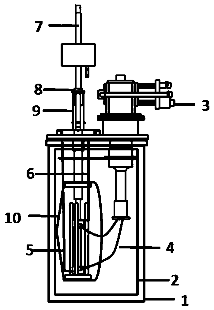
[0027] like figure 1 As shown, the performance measurement device of the conduction cooled superconducting wire of the present invention includes a vacuum dewar 1 , a temperature control assembly, an electrical assembly, a supporting device, a fixture and a loading rod 7 .

[0028] Temperature control components, electrical components, supporting devices and fixtures are placed inside the vacuum dewar 1 , and the loading rod 7 is arranged on the central axis outside the vacuum dewar 1 . The superconducting wire is supported by a fixture and arranged in the vacuum dewar 1 . A radiation shield 2 is installed inside the vacuum dewar 1 .

[0029] The temperature control component is cooled by the refrigerator 3 installed outside the vacuum dewar 1, and the cold energy is conducted to the clamps at both ends of the superconducting wire through the...


PUM


Abstract

The invention discloses a superconducting wire performance measuring device based on conduction cooling. The superconducting wire performance measuring device comprises a temperature control assembly,a loading rod, a vacuum Dewar, a supporting device, an electrical assembly and a clamp. The temperature control assembly is cooled through a refrigerating machine installed on a flange of an end plate of the vacuum Dewar, a thermometer is installed on a superconducting wire to measure the temperature of the superconducting wire, an anti-radiation screen is installed in the vacuum Dewar, and the electrical assembly feeds the superconducting wire through a current lead and measures electrical signals at the two ends of the superconducting wire. The loading rod and the supporting device are usedfor installing the superconducting wire through the clamp and applying a load to the superconducting wire, and a strain gauge is installed on the superconducting wire to measure the strain state of the superconducting wire. The superconducting wire performance measuring device based on conduction cooling is high in operability, simple in structure and capable of achieving low-temperature stress-strain measurement of different temperature sections.

Description

technical field [0001] The invention relates to a performance measuring device of a superconducting wire. Background technique [0002] High-field magnet technology has been one of the research hotspots in the field of superconducting magnets in recent years. During the operation of the high-field coil, a large current is passed through the wire to generate a strong magnetic field. At the same time, the coil needs to work in an extremely low temperature environment to increase the conduction. Therefore, the strong electromagnetic field, high current and extreme low temperature environment make the superconducting coil work in a complex and extreme environment, resulting in the inevitable large stress state and stress concentration phenomenon in the local parts of the magnet, which may cause the magnet to quench. In such complex working conditions, the comprehensive bearing capacity of the entire magnet system is tested, and the manufacture of high-field coils is the most imp...

Claims


Application Information

Patent Timeline
Patent Type & Authority Applications(China)
IPC IPC(8): G01N3/18G01N3/04G01R31/00G01R1/04
CPCG01N3/18G01N3/04G01R31/003G01R1/0425G01N2203/0017G01N2203/0226G01N2203/0228G01N2203/04Y02E40/60
Inventor 孙万硕王秋良程军胜戴银明胡新宁陈顺中王晖刘建华
Owner INST OF ELECTRICAL ENG CHINESE ACAD OF SCI
Learn More