
Three-dimensional steam cavity type phase change heat storage device

A phase-change heat storage and steam cavity technology, applied in heat storage equipment, indirect heat exchangers, heat exchanger types, etc. problems, to achieve the effect of improving heat transfer efficiency, eliminating contact thermal resistance, and improving heat dissipation performance

Inactive Publication Date: 2020-07-10
NANJING 6902 TECH
View PDF10 Cites 4 Cited by
  • Summary
  • Abstract
  • Description
  • Claims
  • Application Information

AI Technical Summary

Problems solved by technology

Relevant application research has made great progress. For example, in the Chinese patent No. ZL201410488344.1, in order to improve the thermal conductivity of the heat storage device, metal foam is filled inside the metal shell of the heat storage device. Although metal foam and metal The inner wall of the shell adopts an interference fit, but the contact thermal resistance between the foam metal and the metal shell is still very large, which affects the overall thermal conductivity of the heat storage device
Another example is the Chinese patent No. ZL201810965310.5, which proposes a phase-change heat storage device for thermal control of aerospace electronic equipment and missile-borne radar. The graphene skeleton is used to improve the heat transfer efficiency of the heat storage device. There is also graphite The contact thermal resistance between the graphene skeleton and the package shell is relatively large, and the cost of graphene is still high

Method used


Image

  • Three-dimensional steam cavity type phase change heat storage device
  • Three-dimensional steam cavity type phase change heat storage device
  • Three-dimensional steam cavity type phase change heat storage device

Examples


Embodiment Construction

[0024] The present invention will be further described in detail below in conjunction with the accompanying drawings and specific embodiments.

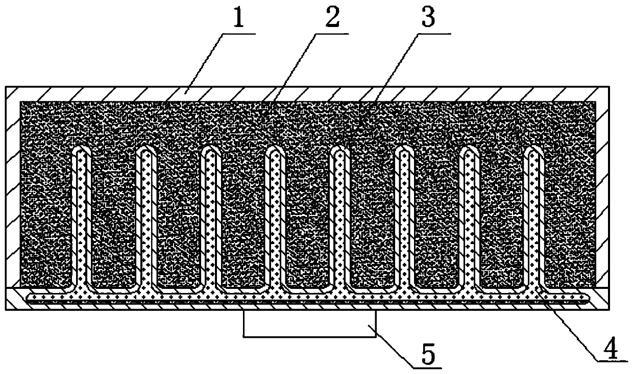
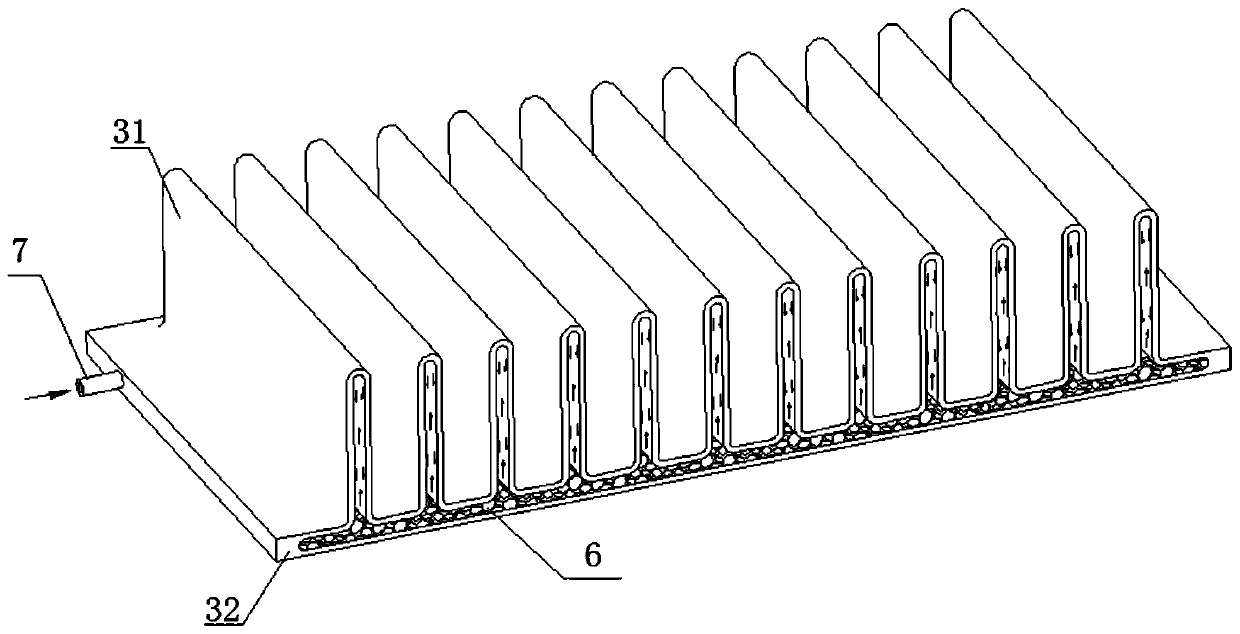
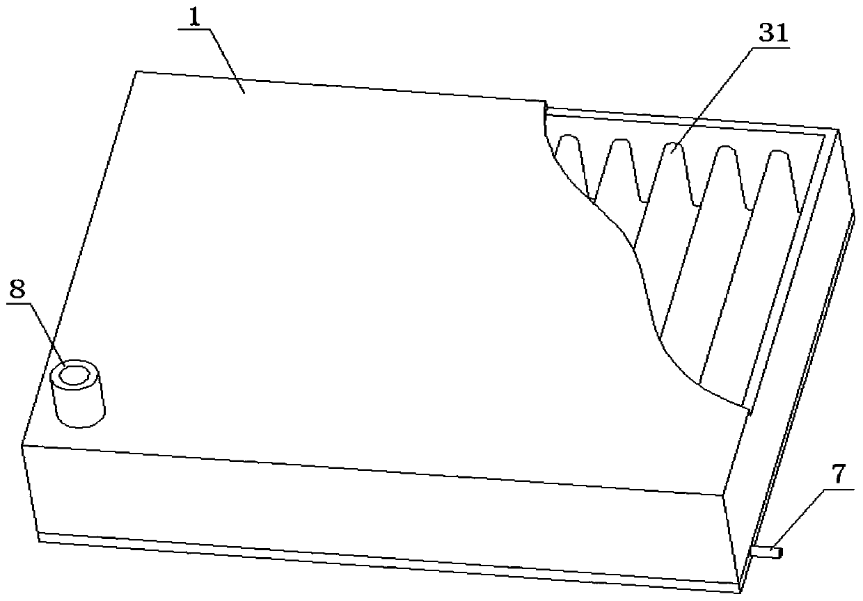
[0025] Please combine Figure 1 to Figure 3 As shown, the present invention provides a three-dimensional steam cavity type phase change heat storage device, which includes a three-dimensional steam cavity 3 and an encapsulation shell 1 covering the three-dimensional steam cavity 3 . The three-dimensional steam cavity 3 includes a heat transfer base plate 32 and a plurality of cooling teeth 31 extending upward from the heat transfer base plate 32 . Both the heat transfer substrate 32 and the heat dissipation teeth 31 are hollow inside. And the internal cavity of the heat transfer substrate is connected with the internal cavity of each cooling tooth, which is called the overall airtight cavity; the three-dimensional steam cavity 3 is connected with the package shell 1 by screwing or welding. A sealed cavity is formed between the packa...


PUM


Abstract

The invention discloses a three-dimensional steam cavity type phase change heat storage device. The device comprises a three-dimensional steam cavity and a packaging shell; the three-dimensional steamcavity comprises a heat transfer substrate and heat dissipation teeth, the heat transfer substrate and the heat dissipation teeth are all hollow structures to form an integrated closed cavity, and aphase change medium is sealed in the steam cavity; a sealed cavity is also formed between the packaging shell and each heat dissipation tooth of the three-dimensional steam cavity, and a proper amountof a phase change material is arranged in the sealed cavity; and one side of the heat transfer substrate of the steam cavity serves as a heat plane, heat flows in from the heat plane and diffuses through the three-dimensional steam cavity to the phase change materials on the outer sides of the heat dissipation teeth. According to the design, based on the characteristics of the good heat diffusionperformance of the three-dimensional steam cavity and the high-efficiency heat absorption of the phase change materials, the novel phase change heat storage device with the high-efficiency heat transfer and heat dissipation performance and the low cost is provided, and the heat dissipation problem under the occasions with the high heat flow density and periodic thermal shock in a limited closed space such as being onboard is solved.

Description

technical field [0001] The invention relates to the field of electronic heat dissipation, and more specifically relates to a heat storage device in which a three-dimensional vapor cavity is combined with a phase change material. Background technique [0002] Aerospace and missile-borne electronic equipment are faced with many restrictions in their work, such as tight and narrow space, volume and weight restrictions, intermittent heat flow impact, and external aerodynamic heating and other harsh conditions. Ordinary air cooling, liquid cooling and other methods are no longer applicable. on this special occasion. Due to the advantages of compact structure, high energy storage density, constant working temperature and reliable performance, phase change heat storage devices have good application prospects in confined and airtight environments. [0003] In the field of electronic heat dissipation, phase change heat storage devices have excellent temperature control performance, ...

Claims


Application Information

Patent Timeline
Patent Type & Authority Applications(China)
IPC IPC(8): F28D20/02H05K7/20
CPCF28D20/023H05K7/20509Y02E60/14
Inventor 王军段勇军
Owner NANJING 6902 TECH
Learn More