Boiler flue gas waste heat recycling system based on heat exchanging absorption tower and method

A waste heat recovery system and boiler flue gas technology, applied in the field of flue gas waste heat recovery, can solve the problems of low energy utilization rate of boiler system, reduced load of denitrification device, high equipment investment cost, etc., to prevent dust accumulation and save desulfurization device , The effect of reducing maintenance costs

Inactive Publication Date: 2020-07-10
SOUTH CHINA UNIV OF TECH +1
View PDF5 Cites 0 Cited by
  • Summary
  • Abstract
  • Description
  • Claims
  • Application Information

AI Technical Summary

Problems solved by technology

[0007] Aiming at the problems of low energy utilization rate of the boiler system, substandard flue gas emission, complex process flow, high equipment investment cost, low-temperature corrosion of economizer, etc., the present invention integrates desulfurization, denitrification and heat exchange by setting up a heat exchange absorption tower, increasing Flue gas and heat exchanger heat transfer coefficient, improve heat transfer efficiency, increase economizer inlet water temperature, save desulfurization device, and use ammonia water to absorb by-product nitrogen fertilizer, crystallization device waste water enters ammonia solution feeding device for recycling; after heat exchange The main pollutant in the flue gas behind the absorption tower is NO, and the flue gas is partially circulated and directly mixed with fresh air for preheating, thereby saving the air preheater and suppressing the concentration of nitrogen oxides in the furnace, making the denitrification device load reduction

Method used


Image

  • Boiler flue gas waste heat recycling system based on heat exchanging absorption tower and method

Examples


Embodiment Construction

[0029] In order to better understand the present invention, the present invention will be further described below in conjunction with the accompanying drawings, but the embodiments of the present invention are not limited thereto.

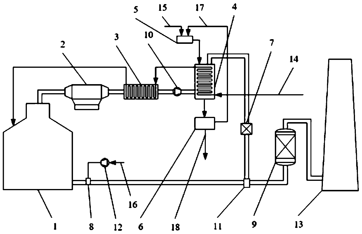
[0030] Such as figure 1As shown, a boiler flue gas waste heat recovery system based on heat exchange and absorption tower, including boiler 1, electrostatic precipitator 2, economizer 3, booster fan 10, heat exchange and absorption tower 4, ammonia solution feeding device 5, crystallization Device 6, water eliminator 7, air mixer 8, induced draft fan 12, splitter 11, denitrification device 9 and chimney 13; heat exchange coil is arranged inside heat exchange absorption tower 4; There are smoke inlet and water inlet, the bottom of the tower kettle is equipped with a material outlet, and the top of the tower is respectively equipped with a smoke outlet and a material inlet; the smoke outlet of the boiler 1 is connected to the smoke inlet of the elect...


PUM


Abstract

The invention discloses a boiler flue gas waste heat recycling system based on a heat exchanging absorption tower and a method, and belongs to the technical field of flue gas waste heat recycling anddisposal. According to the system, a heat exchanging coil pipe is arranged inside the heat exchanging absorption tower; a flue gas outlet of a boiler communicates with a flue gas inlet of an electrostatic dust remover; a flue gas outlet of the electrostatic dust remover communicates with a flue gas inlet of an economizer; an flue gas outlet of the economizer communicates with a flue gas inlet of the heat exchanging absorption tower; an flue gas outlet of the heat exchanging absorption tower communicates with a flue gas inlet of a dehydrator; a flue gas outlet of the dehydrator communicates with a diverter; the diverter communicates with a denitration device and an air mixer respectively; the air mixer communicates with a draught fan and is connected with an air inlet at the bottom of the boiler; and the denitration device communicates with a chimney. Via the arrangement of the heat exchanging absorption tower, the functions of desulfuration, denitration and heat exchange are integrated, flue gas is in direct contact with ammonia, and water inflow in the heat exchanging coil pipe from the boiler is heated, so the heat transfer coefficient is increased, heat transfer efficiency is improved, the temperature of water inflow in the economizer is increased, low-temperature corrosion of the economizer is lessened, and a desulfuration device is omitted.

Description

[0001] field of invention [0002] The invention relates to a flue gas waste heat recovery technology, in particular to a boiler flue gas waste heat recovery system and method based on a heat exchange absorption tower. Background technique [0003] With the continuous development of social economy, the demand for energy is becoming increasingly tense, and the requirements for environmental protection are getting higher and higher. Boilers are the main thermal power equipment, and flue gas is the main way for boilers to waste energy. In the use of industrial boilers, there are generally problems such as low energy utilization rate, high exhaust gas temperature, and excessively high pollution components in flue gas. [0004] Existing boiler flue gas waste heat recovery systems generally include boilers, economizers, air preheaters, and desulfurization and denitrification devices. After the cold water enters the economizer, due to the large temperature difference, low-temperatur...

Claims


Application Information

Patent Timeline
Patent Type & Authority Applications(China)
IPC IPC(8): F28D7/08F23L15/04F23J15/06F23J15/02F22D1/24
CPCF22D1/24F23J15/022F23J15/06F23L15/04F28D7/082Y02E20/34
Inventor 江燕斌彭威建叶志光杨守红谭泽
Owner SOUTH CHINA UNIV OF TECH
Why Eureka
Try Eureka