
Plasma cleaning device of coated substrate, and use method of plasma cleaning device

A plasma cleaning and substrate technology, applied in the direction of ion implantation plating, sputtering plating, gaseous chemical plating, etc., can solve the problems of uneven coverage, low ionization rate of cleaning medium, affecting the quality of coating, etc., to avoid Overheating damage, good cleaning effect, high application value effect

Pending Publication Date: 2020-07-10
辽宁北宇真空科技有限公司
View PDF6 Cites 4 Cited by
  • Summary
  • Abstract
  • Description
  • Claims
  • Application Information

AI Technical Summary

Problems solved by technology

[0003] However, the plasma cleaning device and cleaning technology in the prior art have poor cleaning effect on the substrate, that is, the pure plasma cleaning device has limited energy, uneven coverage, and the low ionization rate of the cleaning medium makes it difficult to achieve fast and complete cleaning. The effect of evenly cleaning the surface of the substrate not only affects the work efficiency, but also the incomplete or uneven cleaning of the substrate may affect the uniformity of the substrate, thereby affecting the quality of the subsequent coating film

Method used


Image

  • Plasma cleaning device of coated substrate, and use method of plasma cleaning device
  • Plasma cleaning device of coated substrate, and use method of plasma cleaning device
  • Plasma cleaning device of coated substrate, and use method of plasma cleaning device

Examples


Embodiment 1

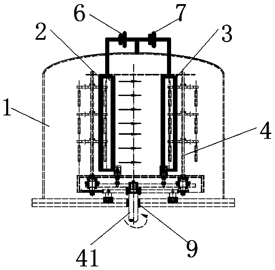
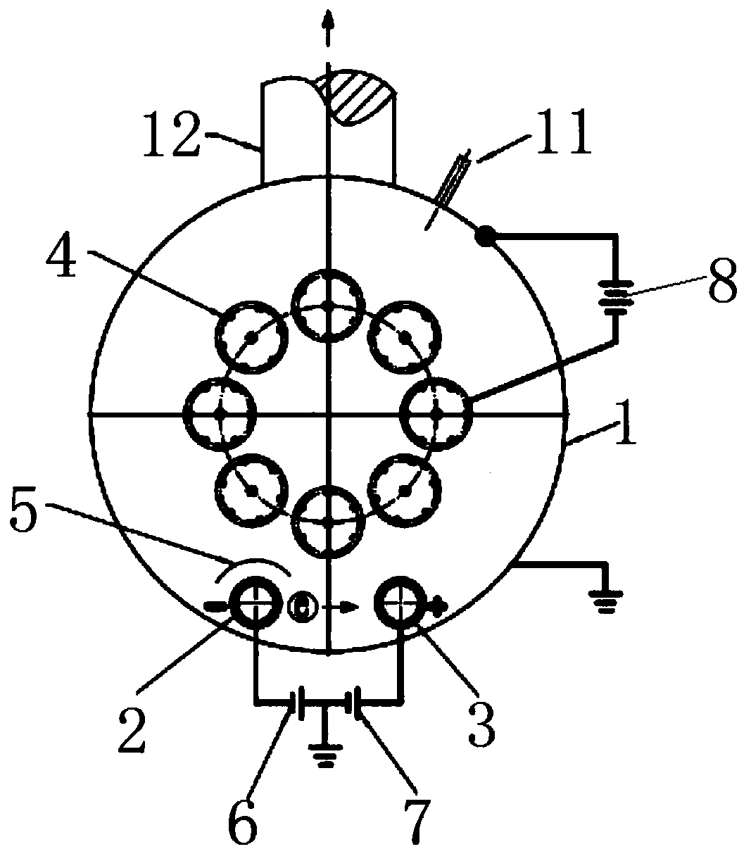
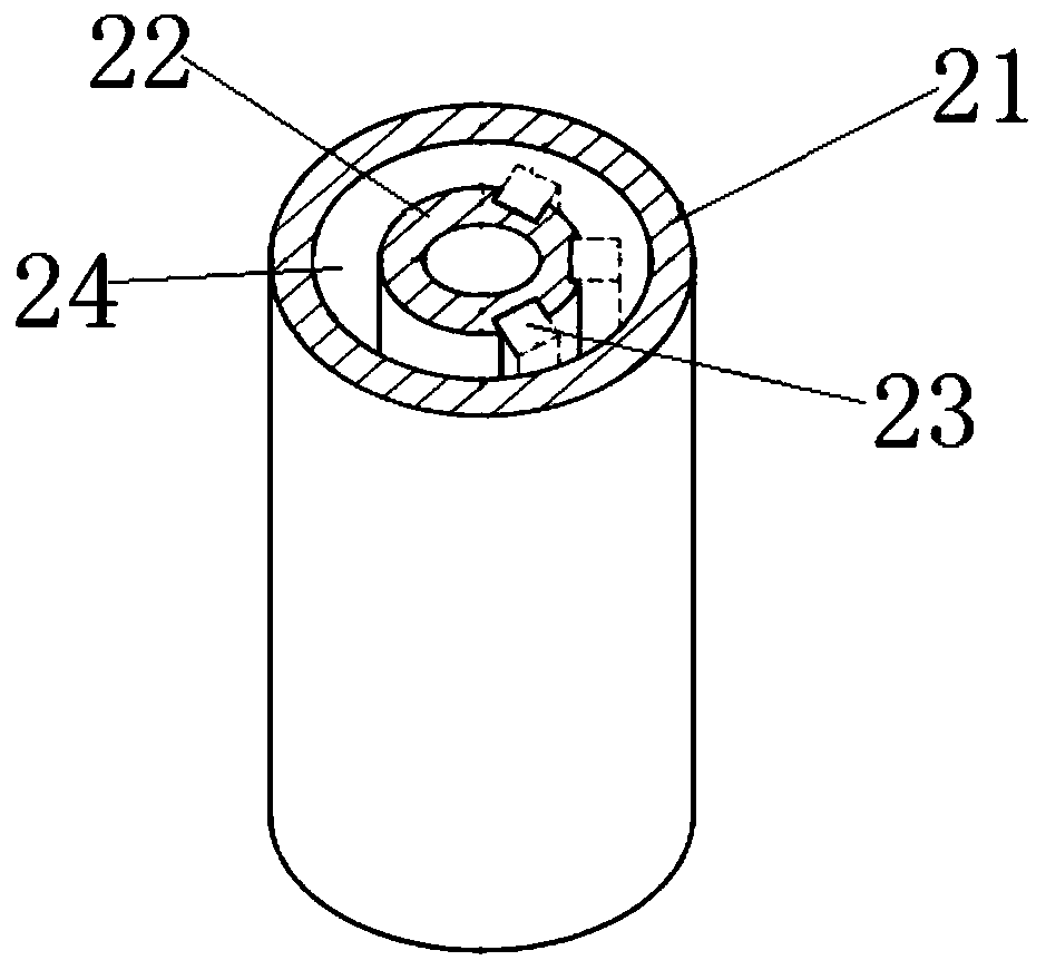
[0035] As attached Figure 1-2 As shown, a plasma cleaning device for coated substrates includes a vacuum chamber 1, which has a gas-filling hole 11 and a suction hole 12, and also includes an ionizing cathode 2, an ionizing anode 3, a workpiece holder 4, and a workpiece holder 4 located in the vacuum chamber 1. Baffle 5 and ionization source one 6, ionization source two 7, and power source 8 located outside the vacuum chamber;

[0036] The anode grounded cathode of the ionization source 6 is connected to the ionization cathode 2, the cathode grounded of the ionization source 2 7 is connected to the ionization anode 3, the anode grounded cathode of the power supply 8 is connected to the workpiece holder 4, and the baffle 5 is located between the ionization cathode 2 and the workpiece holder 4. And the height is equal to the vacuum chamber 1;

[0037] The workpiece holder 4 is rotationally sealed and connected with the bottom end of the vacuum chamber 1.

[0038] As attached Figure ...


PUM

PropertyMeasurementUnit
magnetic flux densityaaaaaaaaaa

Abstract

The invention discloses a plasma cleaning device for a coated substrate and a use method of the plasma cleaning device. The plasma cleaning device comprises a vacuum chamber which is provided with aninflation hole and an exhaust hole; the plasma cleaning device also comprises an ionization cathode, an ionization anode, a workpiece rack and a baffle plate which are located in the vacuum chamber, and an ionization source I, an ionization source II and a power supply which are located outside the vacuum chamber; an anode grounding cathode of the ionization source I is connected with the ionization cathode, a cathode grounding anode of the ionization source II is connected with the ionization anode, and an anode grounding cathode of the power supply is connected with the workpiece rack. Ionized electrons directionally move under the action of cathode and anode electromagnetic fields, and collide with working gas atoms in the moving process to enable the working gas atoms to be positivelycharged, so that dense positively charged ions and negatively charged electrons are formed in the vacuum chamber, and the positively charged ions continuously move towards a workpiece with negative high voltage at a high speed so as to remove pollutants on the workpiece surface when impacting the surface of the workpiece, thereby achieving a cleaning effect; and deeper pollutants can be cleaned away through the cleaning mode, the cleaning effect is good, the efficiency is high, and the high application value is achieved.

Description

Technical field [0001] The invention relates to the technical field of ion plating equipment, in particular to a plasma cleaning device for a coated substrate and a method of use thereof. Background technique [0002] Vacuum coating is a common coating technology in the prior art. Before vacuum coating, it is often necessary to clean the substrate. Only the surface of the workpiece is cleaned with detergent. It is difficult to remove the stains penetrating the substrate surface and the oxidation of the workpiece surface. Therefore, plasma cleaning is often used in the prior art. The principle of plasma cleaning is to generate high-energy disordered plasma in a vacuum chamber through a radio frequency power supply under a certain pressure. The surface of the product is cleaned to achieve the purpose of cleaning, that is, the plasma generated by the radio frequency power supply in a vacuum environment bombards the surface of the substrate, thereby effectively removing the stains th...

Claims


Application Information

Patent Timeline
Patent Type & Authority Applications(China)
IPC IPC(8): C23C14/02C23C16/02
CPCC23C14/022C23C16/0245
Inventor 关秉羽
Owner 辽宁北宇真空科技有限公司
Learn More