Protective device of solar Stirling engine heat absorber
A Stirling engine and protection device technology, applied in the direction of solar thermal devices, solar collectors, solar collector safety, etc., can solve the problem that the engine is in a safe state, removed, etc.
- Summary
- Abstract
- Description
- Claims
- Application Information
AI Technical Summary
Problems solved by technology
Method used
Image
Examples
Embodiment 1
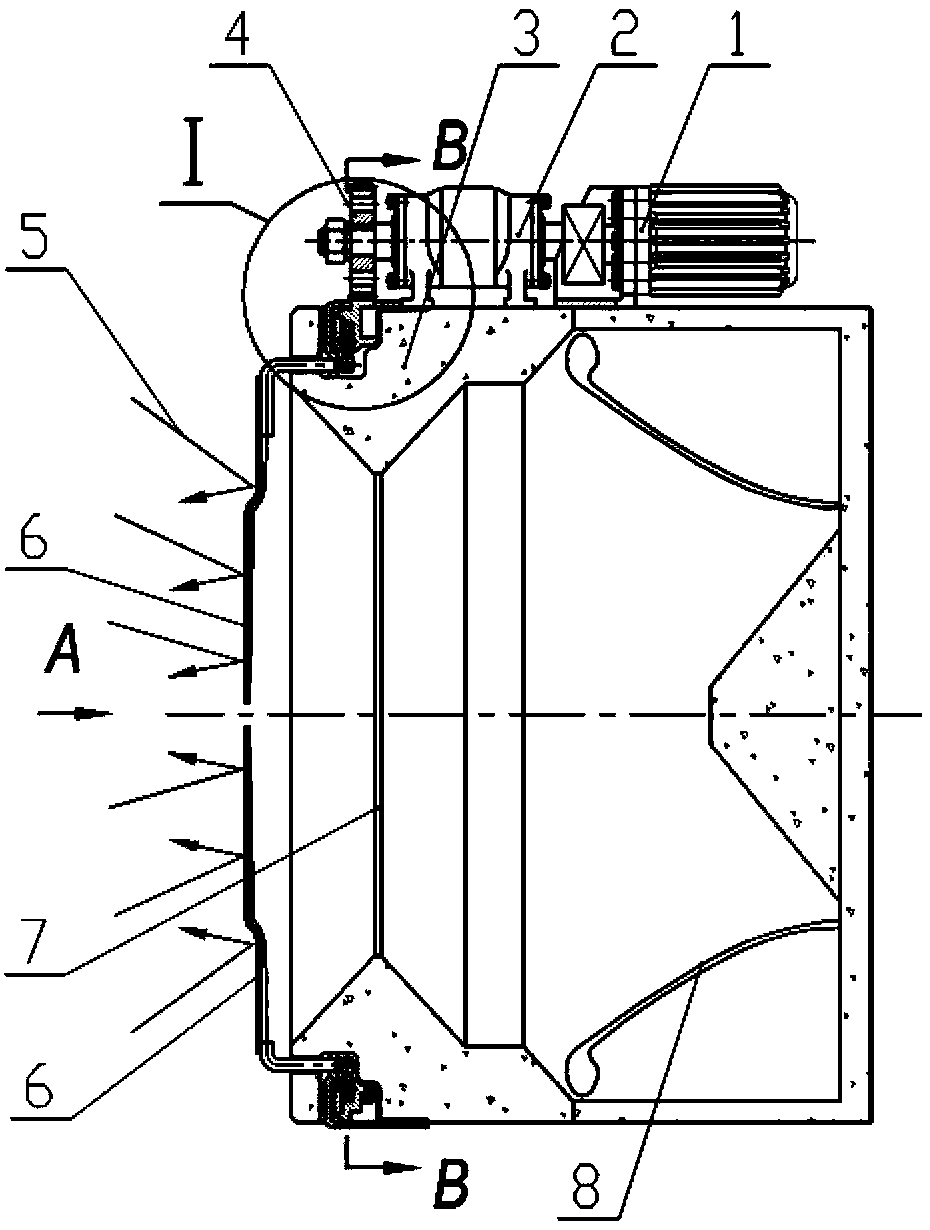
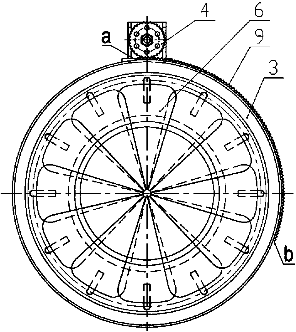
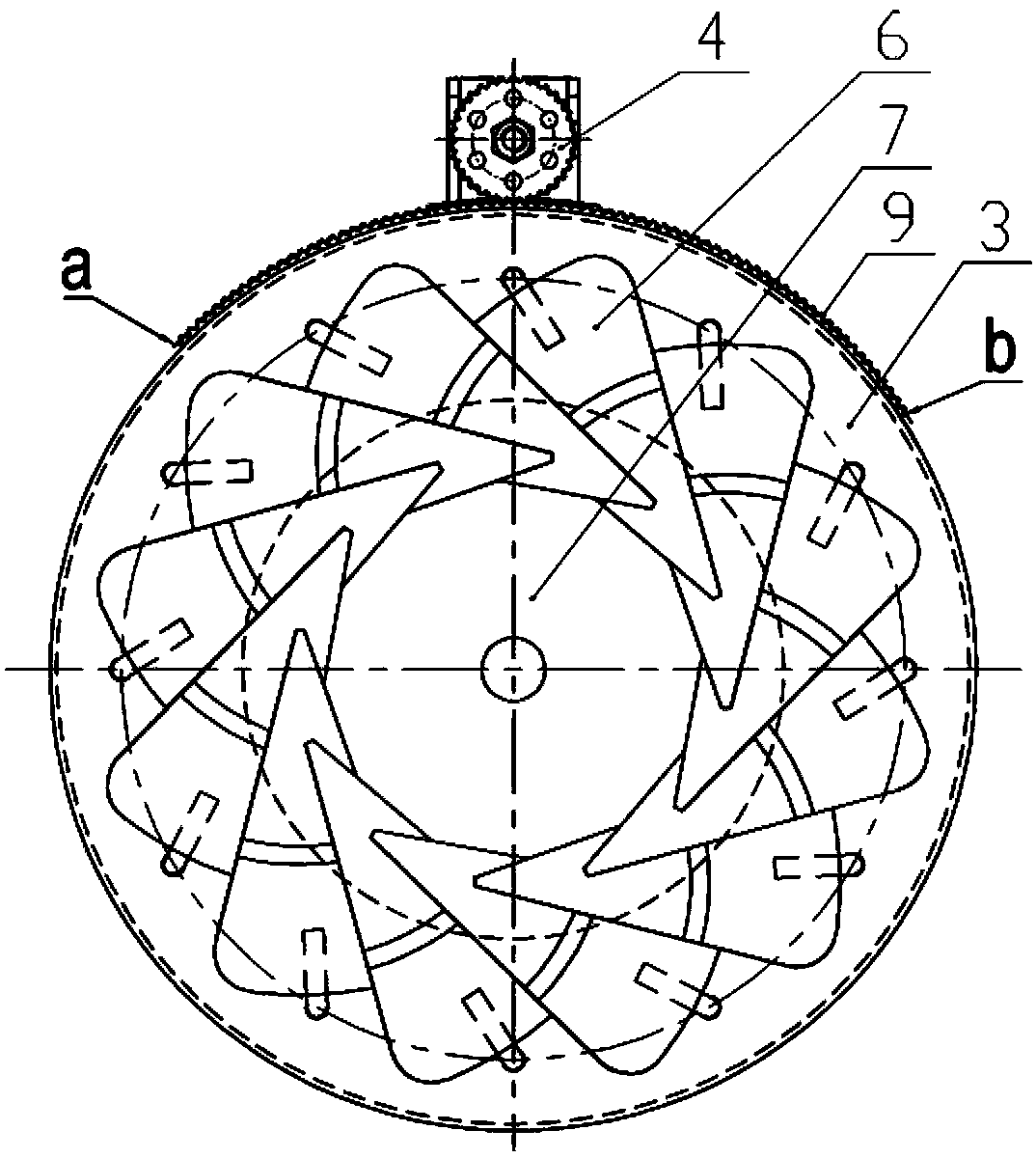
[0041] Please refer to figure 1 , figure 2 , image 3 , Figure 4 , Figure 5 , Figure 6 and Figure 7 , figure 1 It is a front sectional view of the first specific embodiment of the protection device of the solar Stirling engine heat absorber provided by the present invention, and also shows a state diagram of the cover plate in the first position; figure 2 for figure 1 The A-direction view of , and shows the state diagram of the cover plate in the first position; image 3 for figure 1 The A-direction view of , and shows the state diagram of the cover plate in the second position; Figure 4 for figure 1 The A-direction view of , and shows the state diagram of the cover plate in the third position; Figure 5 for figure 1 The A-direction view of , and shows the state diagram of the cover plate in the fourth position; Figure 6 for figure 1 Partial enlarged view of Ⅰ; Figure 7 for figure 1 B-B direction sectional view.
[0042] In a specific embodiment, the so...
Embodiment 2
[0052] Please refer to Figure 8 , Figure 9 and Figure 10 , Figure 8 It is a front sectional view of the second specific embodiment of the solar Stirling engine protection device provided by the present invention, and also shows a state diagram of the cover plate in the first position; Figure 9 for Figure 8 C-C direction sectional view; Figure 10 for Figure 8 Partial enlarged view of Ⅱ.
[0053] The difference between this embodiment and embodiment 1 is:
[0054] 1) The rotating shaft 16 is fixed on the supporting ring 13, and the protruding end is provided with a driven gear 18, the driving ring 11 is provided with an inner ring gear 17, and the driven gear 18 is meshes with the ring gear 17. Cancel pressure ring 12, sliding ball 14, driving lever 15 and other parts.
[0055] 2) When it is necessary to adjust the input light energy of the daylight opening 7 of the heat absorber, when the driver 1 makes the drive ring 11 rotate around the central axis of the he...
Embodiment 3
[0057] Please refer to Figure 11 and Figure 12 , Figure 11 It is a front sectional view of the third specific embodiment of the protection device of the solar Stirling engine heat absorber provided by the present invention, and also shows a state diagram of the cover plate in the first position; Figure 12 for Figure 11 E-E to the sectional view.
[0058] The difference between this embodiment and embodiment 2 is:
[0059] 1) Cancel the drive ring 11, the drive gear 4, and the driven gear 18, and correspondingly set the first sprocket 10 at the power output end of the transmission 2, and set the second sprocket at the top of the shaft 16 20, connected by a chain 19 between the first sprocket 10 and the second sprocket 20;
[0060] 2) When it is necessary to adjust the input light energy of the daylighting port 7 of the heat absorber, the driver 1 rotates the first sprocket 10 through the transmission mechanism 2, drives the chain 19 to move, and drives all the second ...
PUM
 Abstract
Description
Claims
Application Information
 - R&D
- Intellectual Property
- Life Sciences
- Materials
- Tech Scout
- Unparalleled Data Quality
- Higher Quality Content
- 60% Fewer Hallucinations
Browse by: Latest US Patents, China's latest patents, Technical Efficacy Thesaurus, Application Domain, Technology Topic, Popular Technical Reports.
© 2025 PatSnap. All rights reserved.Legal|Privacy policy|Modern Slavery Act Transparency Statement|Sitemap|About US| Contact US: help@patsnap.com


