
A waste heat recovery system for high temperature liquid slag

A waste heat recovery system and liquid slag technology, applied in the direction of recycling technology, etc., can solve the problems of no waste heat recovery, large cooling water consumption, high-pressure steam polluting the surrounding environment, etc., and achieve the effect of improving the utilization rate of waste heat and reducing the amount of consumption.

Active Publication Date: 2021-07-02
ANHUI UNIVERSITY OF TECHNOLOGY
View PDF10 Cites 0 Cited by
  • Summary
  • Abstract
  • Description
  • Claims
  • Application Information

AI Technical Summary

Problems solved by technology

[0009] The purpose of the present invention is to solve the problems that the existing high-temperature liquid slag and high-quality energy recovery equipment consume a large amount of cooling water, the high-pressure steam pollutes the surrounding environment, and the waste heat is basically not recovered. It provides a waste heat recovery system for high-temperature liquid slag. A small amount of cooling water can fully exchange heat in the high-temperature liquid slag inside the slag quick-cooling high-pressure tank, and generate a large amount of steam that can be recycled, which improves the utilization rate of waste heat resources, and the structure of the whole device is relatively simple, which greatly reduces the manufacturing cost. cost

Method used


Image

  • A waste heat recovery system for high temperature liquid slag
  • A waste heat recovery system for high temperature liquid slag
  • A waste heat recovery system for high temperature liquid slag

Examples


Embodiment 1

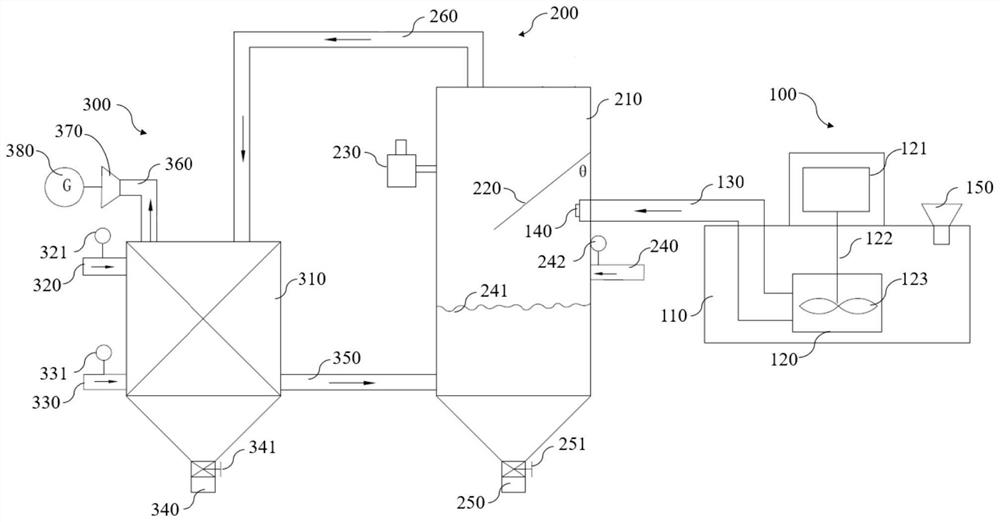
[0059] A waste heat recovery system for high-temperature liquid slag in this embodiment includes three parts: a slag receiving unit 100, a molten slag quick cooling unit 200, and a recovery unit 300, wherein the slag receiving unit 100 is used to receive high-temperature liquid slag, while the slag receiving unit 100 also transports the high-temperature liquid slag to the slag rapid cooling unit 200 under a certain pressure; It refers to giving the high-temperature liquid slag an instantaneous impact force, causing it to disperse into small liquid droplets, fall into the cooling water 241 and solidify into an amorphous glass phase to be discharged. pressure; at the same time, the recovery unit 300 exchanges heat with soft water for the mixed steam in the slag quick cooling unit 200, and the clean steam formed by the heat exchange is recycled, that is, heat energy is converted into electric energy.

[0060] Concrete combination figure 1 Specifically, the slag receiving unit 10...

Embodiment 2

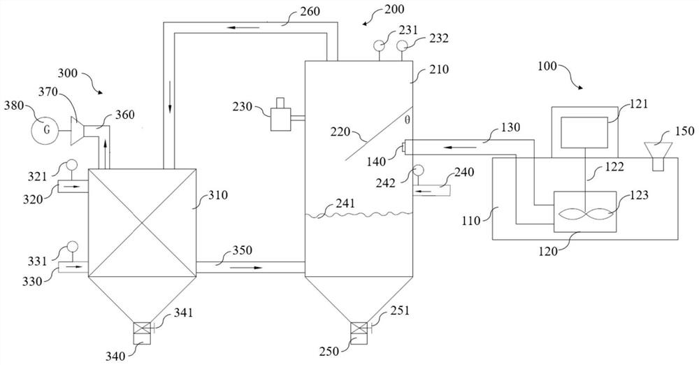
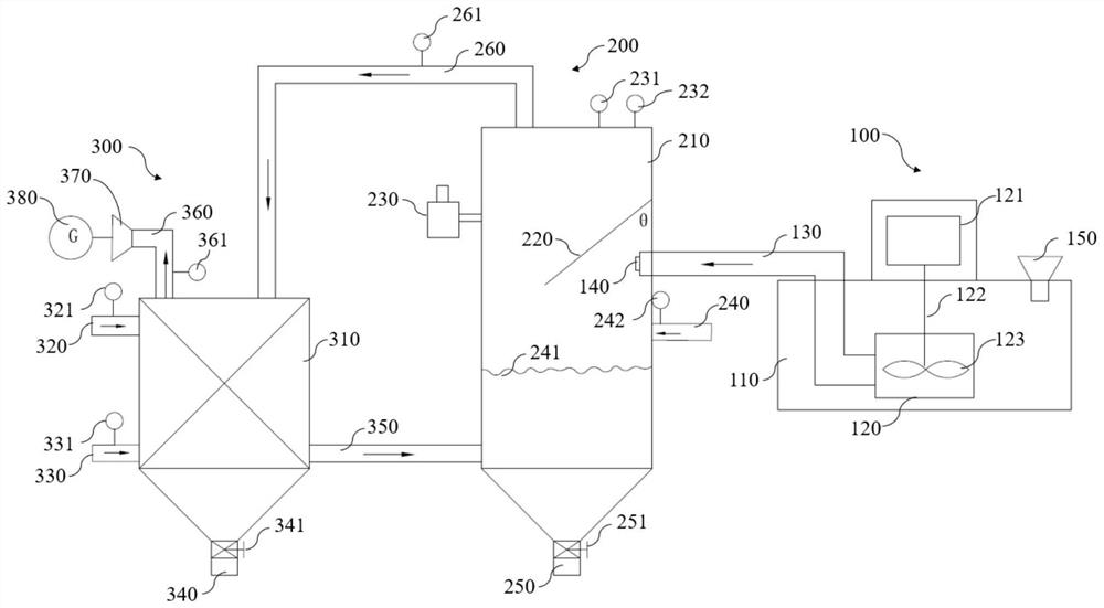
[0067] This embodiment is basically the same as Embodiment 1, except that the deflector 220 forms an included angle of 80° with the inner wall of the molten slag quick-cooling high-pressure tank 210, and the swirl nozzle 140 beats the high-temperature liquid slag at a pressure of 500Kpa. On the deflector 220; at the same time, the slag rapid cooling unit 200 also includes a pressure gauge 231 and a pressure relief valve 232, that is, a pressure gauge 231 and a pressure relief valve 232 are installed above the slag rapid cooling high-pressure tank 210, and the slag rapid cooling The pressure in the high pressure tank 210 should be kept within a stable range of 480kPa. During normal operation of the system, if the pressure in the tank is higher than the value range, it will be monitored by the pressure gauge 231, and the pressure reducing valve 232 should be adjusted accordingly to reach the normal range, such as figure 2 Shown; Correspondingly, the pressure of high pressure wat...

Embodiment 3

[0069]The inventor tried to change the angle of the deflector 220 and the output pressure of the high-temperature pump 120 to study the particle size of the solidified amorphous glass phase in the slag quick-cooling high-pressure tank 210, and wanted to obtain as much solid slag as possible, so as to make full use of the high-temperature liquid slag energy, reduce the post-treatment process of solid slag, and make it easy to recycle to the cement plant for use. It is found that the high-temperature liquid slag reaches the position of the deflector 220 (the angle between the deflector 220 and the vertical direction is between 20-80°C), when the pressure of the high-temperature pump 120 is too high, the angle between the deflector 220 and the vertical direction If the included angle is too small, high-temperature slag will splash on the side wall of the slag quick-cooling high-pressure tank 210. After a long time, too much liquid slag will accumulate on the side wall, wear the sl...


PUM


Abstract

The invention discloses a waste heat recovery system for high-temperature liquid slag, and relates to high-temperature liquid slag and high-quality energy recovery equipment in the metallurgical industry. It includes a slag receiving unit, a slag rapid cooling unit and a recovery unit; the slag receiving unit is used to receive high-temperature liquid slag, and the slag receiving unit sprays high-temperature liquid slag into the molten slag rapid cooling unit at a certain pressure through a high-temperature pump; The slag rapid cooling unit granulates the high-temperature liquid slag into small droplets under strong cooling conditions and high pressure conditions, and falls into the cooling water in the slag rapid cooling unit to transform into granular amorphous glass phase and discharges the recovery unit The mixed steam in the slag rapid cooling unit is exchanged with soft water for waste heat power generation or industrial use, wherein the pressure of the high temperature liquid slag delivered by the slag receiving unit is greater than the pressure in the slag rapid cooling unit. The invention can greatly improve the waste heat utilization rate of high-temperature liquid slag treatment, reduce the consumption of cooling water, and is beneficial to energy saving and emission reduction of iron and steel enterprises.

Description

technical field [0001] The invention belongs to the field of high-temperature liquid slag and high-quality energy recovery equipment in the metallurgical industry, and more specifically relates to a waste heat recovery system for high-temperature liquid slag. Background technique [0002] In iron and steel production, high-quality steam mainly uses water-quenched blast furnace slag process at home and abroad, which will form a large amount of low-quality warm water and saturated steam, but it is difficult to be recycled, and about 15% of the slag washing water will evaporate and absorb heat Turning into water vapor and releasing it not only causes a waste of energy and water resources, but also contains a large amount of harmful substances (hydrogen sulfide, sulfur dioxide) in the water vapor, which seriously pollutes the environment. [0003] For a long time, many researchers have studied this problem, and designed blast furnace slag such as wind quenching method, double co...

Claims


Application Information

Patent Timeline
Patent Type & Authority Patents(China)
IPC IPC(8): C21B3/06C21B3/08
CPCC21B3/06C21B3/08C21B2400/024C21B2400/034C21B2400/062C21B2400/066C21B2400/08Y02W30/50
Inventor 陈光包向军葛庆世徐超成张璐
Owner ANHUI UNIVERSITY OF TECHNOLOGY
Learn More