
Hole filling method based on dense disparity map and vehicle-mounted equipment

A dense disparity map and hole filling technology, which is applied in the field of binocular vision and can solve problems such as poor hole point processing effect.

Active Publication Date: 2020-07-07
HISENSE
View PDF10 Cites 0 Cited by
  • Summary
  • Abstract
  • Description
  • Claims
  • Application Information

AI Technical Summary

Problems solved by technology

[0006] In view of this, the present invention provides a hole filling method based on dense disparity map and vehicle-mounted equipment to solve the problem in the prior art that the processing effect of hole points in dense disparity map is poor

Method used


Image

  • Hole filling method based on dense disparity map and vehicle-mounted equipment
  • Hole filling method based on dense disparity map and vehicle-mounted equipment
  • Hole filling method based on dense disparity map and vehicle-mounted equipment

Examples


Embodiment Construction

[0038] Reference will now be made in detail to the exemplary embodiments, examples of which are illustrated in the accompanying drawings. When the following description refers to the accompanying drawings, the same numerals in different drawings refer to the same or similar elements unless otherwise indicated. The implementations described in the following exemplary embodiments do not represent all implementations consistent with this application. Rather, they are merely examples of apparatuses and methods consistent with aspects of the present application as recited in the appended claims.

[0039] The terminology used in this application is for the purpose of describing particular embodiments only, and is not intended to limit the application. As used in this application and the appended claims, the singular forms "a", "the", and "the" are intended to include the plural forms as well, unless the context clearly dictates otherwise. It should also be understood that the term...


PUM


Abstract

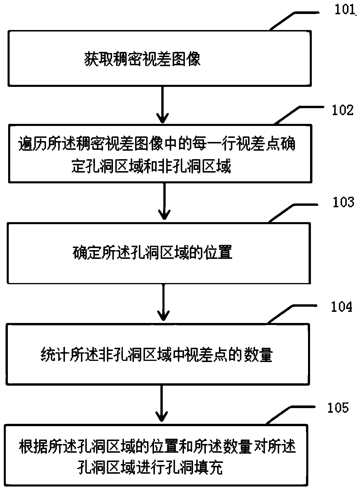
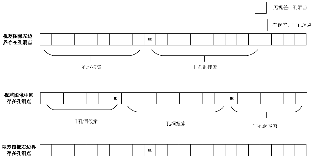
The invention provides a hole filling method based on a dense disparity map and vehicle-mounted equipment. The method comprises: acquiring a dense disparity image, traversing each row of parallax points in the dense parallax image to determine a hole region and a non-hole region, determining the position of the hole area, counting the number of parallax points in the non-hole area, and carrying out hole filling on the hole areas according to the positions and the number of the hole areas. According to the invention, hole areas can be searched line by line, and then the searching result is accurate; and, in addition, hole filling can be carried out according to the positions of the hole areas and the number of parallax points of the non-hole areas, so that large plaque noise of the non-texture areas can be effectively removed, hole parallax is filled, smooth dense parallax is obtained, and consumed hardware resources can be reduced.

Description

technical field [0001] The invention relates to the technical field of binocular vision, in particular to a hole filling method based on a dense disparity map and a vehicle-mounted device. Background technique [0002] The principle of binocular stereo vision is to recognize the three-dimensional information of the scene by simulating the human eyes, that is, to obtain the two-dimensional image of the scene from two angles, and then to obtain the parallax image by establishing the matching relationship between the images, and then according to the principle of triangulation, to obtain The depth information of the original image mainly includes the main processes of camera calibration, image correction, and binocular image matching. The establishment of the corresponding relationship between the pixels of the two images is the process of stereo matching, which is also the core process of binocular stereo vision. [0003] There are two main types of existing binocular stereo m...

Claims


Application Information

Patent Timeline
Patent Type & Authority Applications(China)
IPC IPC(8): G06T5/00
CPCG06T5/77G06T5/70Y02T10/40
Inventor 赵启东赵龙夏克江
Owner HISENSE
Learn More