
Device free of material leaking during mold opening and closing

A technology for opening and closing molds and material leakage, which is applied in the field of injection molds and can solve problems such as material leakage

Pending Publication Date: 2020-07-07
东莞市台塑实业有限公司
View PDF0 Cites 0 Cited by
  • Summary
  • Abstract
  • Description
  • Claims
  • Application Information

AI Technical Summary

Problems solved by technology

[0004] The invention provides a device that does not leak material when opening and closing the mold, aiming to solve the problem of material leakage when opening and closing the mold in the existing injection mold

Method used


Image

  • Device free of material leaking during mold opening and closing
  • Device free of material leaking during mold opening and closing
  • Device free of material leaking during mold opening and closing

Examples


Embodiment 1

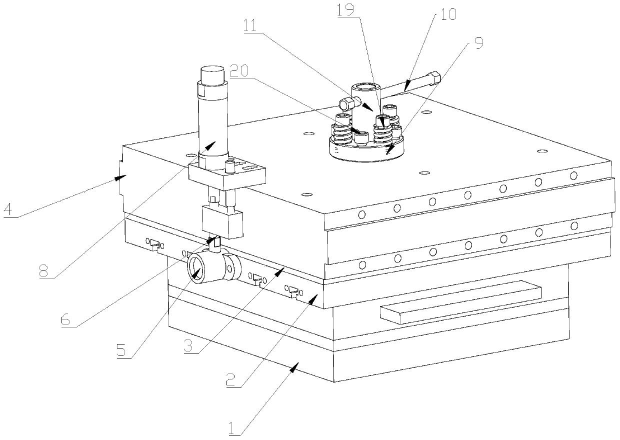
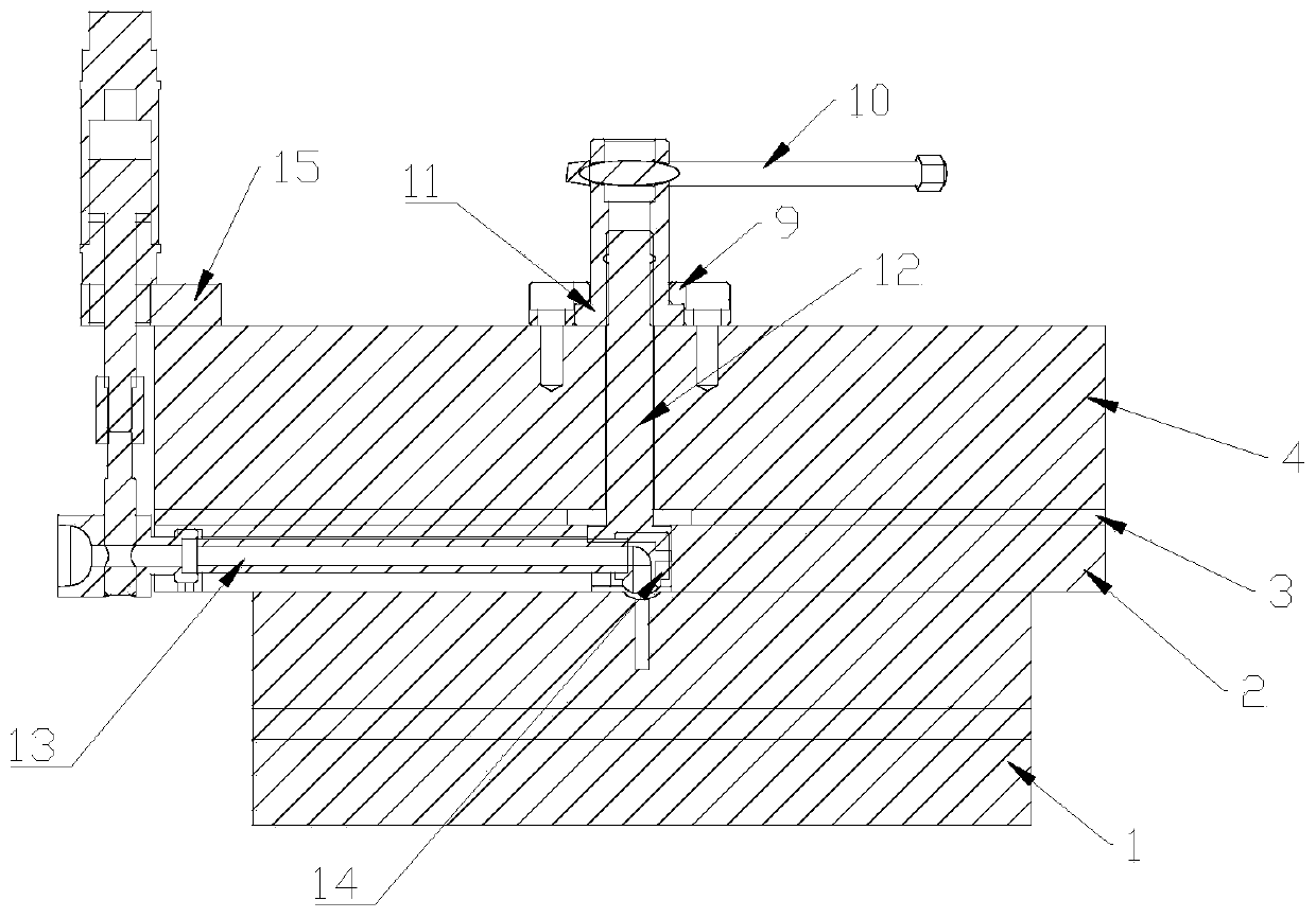
[0020] Such as figure 1 , figure 2 , Figure 4 and Figure 5 As shown, this embodiment provides a device that does not leak material when opening and closing the mold, including a mold 1, the top of the mold 1 is provided with a material inlet, the material inlet communicates with the mold cavity, and the mold 1 is engaged in the guide In the fixed groove 16 of the flow plate 2, an accommodating groove is provided on the side where the deflector 2 and the mold 1 are attached, and a feeding pipe 13 is installed in the accommodating groove, and the feeding pipe 13 feeds The end is fixedly connected to the injection nozzle 5, and the injection nozzle is installed on one side of the deflector 2, and the discharge end of the feeding pipe 13 is fixedly connected to the inlet end 17 of the mold nozzle 14, and the inlet port 17 of the mold inlet The outlet end 18 of the material nozzle 14 corresponds to the feed port on the top of the mold 1 and the outlet end 18 communicates with...

Embodiment 2

[0024] Based on Example 1, such as figure 1 As shown, a heat shield 3 is arranged between the deflector 2 and the upper top cover 4, and the heat shield 3 is fixed on the top of the deflector 2 by screws. When the injection nozzle 5 is injected into the material, it will A large amount of heat will be brought in, which will affect the normal operation of the elements on the upper top cover 4. Then, a heat insulating plate 3 can be arranged between the deflector 2 and the upper top cover 4, so that the heat of the deflector 2 can be insulated and the heat can be prevented. Passed from deflector 2 to upper top cover 4.

Embodiment 3

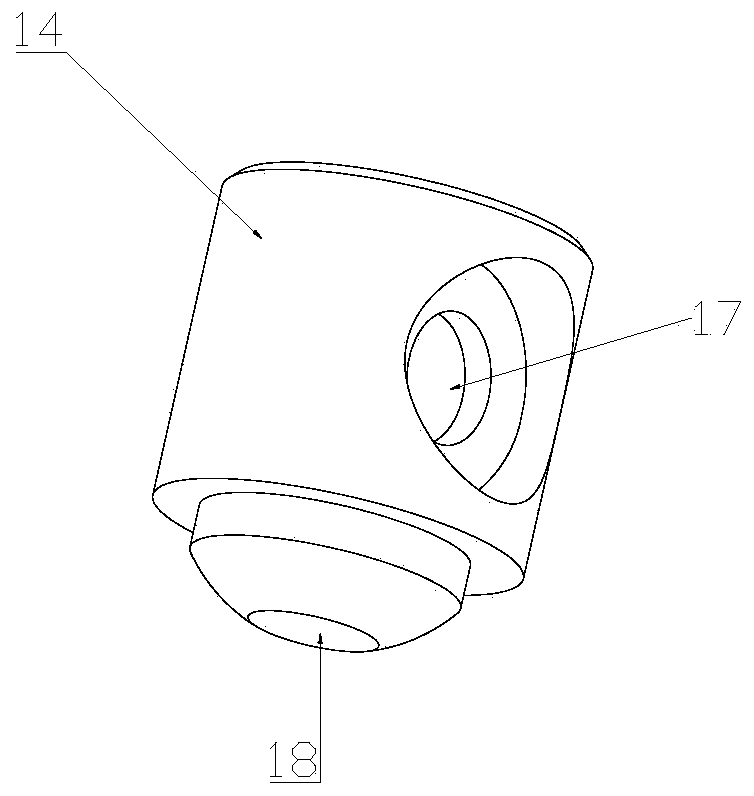
[0026] Based on Example 1, such as image 3 As shown, the inlet end 17 and the outlet end 18 of the mold-injecting nozzle 14 are at a certain angle, and can be elbow-shaped or planar. At a certain angle, the impact force of the material injected from the feeding pipe 13 can be buffered.


PUM


Abstract

The invention is applicable to the field of injection molds, and provides a device free of material leaking during mold opening and closing. The device comprises a mold, a feeding opening is formed inthe top of the mold, a containing groove is formed in the face, attaching to the mold, of a flow guide plate, a feeding pipe is mounted in the containing groove, the feeding end of the feeding pipe is fixedly connected with an injection nozzle, the discharging end of the feeding pipe is fixedly connected with an inlet end of a mold inlet material nozzle, the outlet end of the mold inlet materialnozzle communicates with a feeding opening, the flow guide plate is fixed above the mold, an upper top cover is fixed above the flow guide plate, a mold material nozzle lifting shaft is mounted abovethe mold inlet material nozzle, a mounting groove is formed in the lower end of the mold material nozzle lifting shaft, the mold inlet material nozzle is mounted in a mounting groove of the mold material nozzle lifting shaft, a mold inlet material nozzle fixed plate is mounted on the top of the upper top cover through multiple screw rods, buffer devices are mounted between the screw rods and the mold inlet material nozzle fixed plate, through the buffer devices, the mold inlet material nozzle is attached to an upper mold of the mold, and a material is prevented from being leaked out of the position between the mold inlet material nozzle and the mold.

Description

technical field [0001] The invention belongs to the field of injection molds, in particular to a device that prevents material leakage when opening and closing a mold. Background technique [0002] Injection mold is a tool for producing plastic or rubber products; it is also a tool for giving plastic or rubber products complete structure and precise dimensions. Injection molding is a processing method used in the mass production of certain complex-shaped parts. Specifically, it refers to injecting the melted (or solidified) plastic or rubber into the mold cavity from the injection machine under high pressure, and after cooling or heating and solidifying, a molded product is obtained. The injection mold consists of a moving mold and a fixed mold. The moving mold is installed on the movable template of the injection molding machine, and the fixed mold is installed on the fixed template of the injection molding machine. During injection molding, the movable mold and the fixed...

Claims


Application Information

Patent Timeline
IPC IPC(8): B29C45/26B29C45/17
CPCB29C45/17B29C45/26B29C2045/1784
Inventor 王国华
Owner 东莞市台塑实业有限公司
Learn More