


Quick Research
Generate reliable direction feasibility study reports for your R&D in just a few steps.

Technical Q&A
Discover and master advanced knowledge NOW. Basics, ideas, possibilities, all at once.

Find Solutions
As an expert in R&D theories, this can generate solutions to your technical problems instantly.

Evaluate Feasibility
Analyze your overall solution with one click, know your potential R&D risks in advance.

Monitor Landscape
Get weekly tech updates, stay abreast of the latest tech innovations and key insights.
Metal cutting machine tool for industrial production
A metal cutting and machine tool technology, applied in metal processing machinery parts, metal processing equipment, manufacturing tools, etc., can solve the problems of scratched metal, scratches of cutting head, sand and gravel jamming, etc.
- Summary
- Abstract
- Description
- Claims
- Application Information
AI Technical Summary
Problems solved by technology
Method used
Image

Examples
Embodiment 1
[0031] as attached figure 1 to attach Figure 5 Shown:
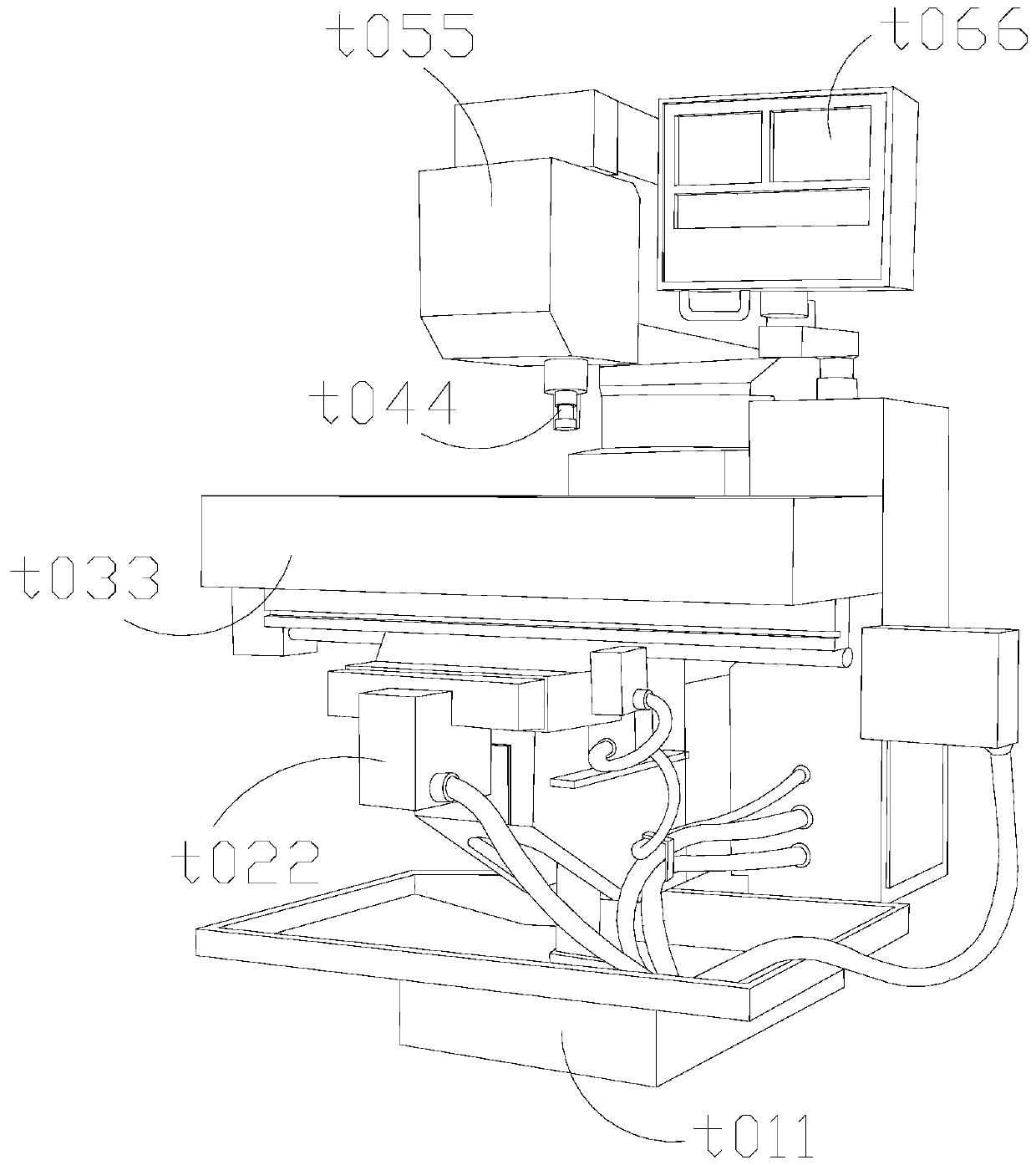
[0032] The invention provides a metal cutting machine tool for industrial production, the structure of which includes a bottom pocket box t011, a lower console t022, an operating platform t033, a cutting head t044, an upper control box t055, and a control panel t066.
[0033] The lower console t022 is arranged above the bottom pocket box t011, the lower console t022 is welded to the lower end surface of the operating platform t033, the cutting head t044 is embedded in the upper control box t055, and the upper control box t055 is installed on the side There is a control panel t066.
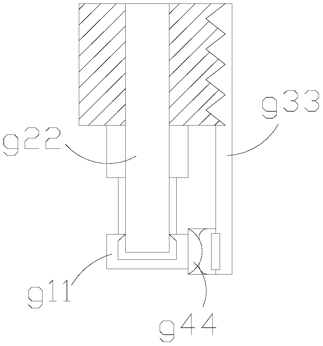
[0034] Wherein, the cutting head t044 includes a cutting ring g11, a middle support rod g22, a support rod g33, and an abutting head g44. The middle support rod g22 is embedded in the cutting ring g11 and is located on the same axis. g33 is connected with the abutment g44, the upper end of the clamping rod g33 is jagged, and the lower end ...
Embodiment 2
[0041] as attached Figure 6 to attach Figure 8 Shown:
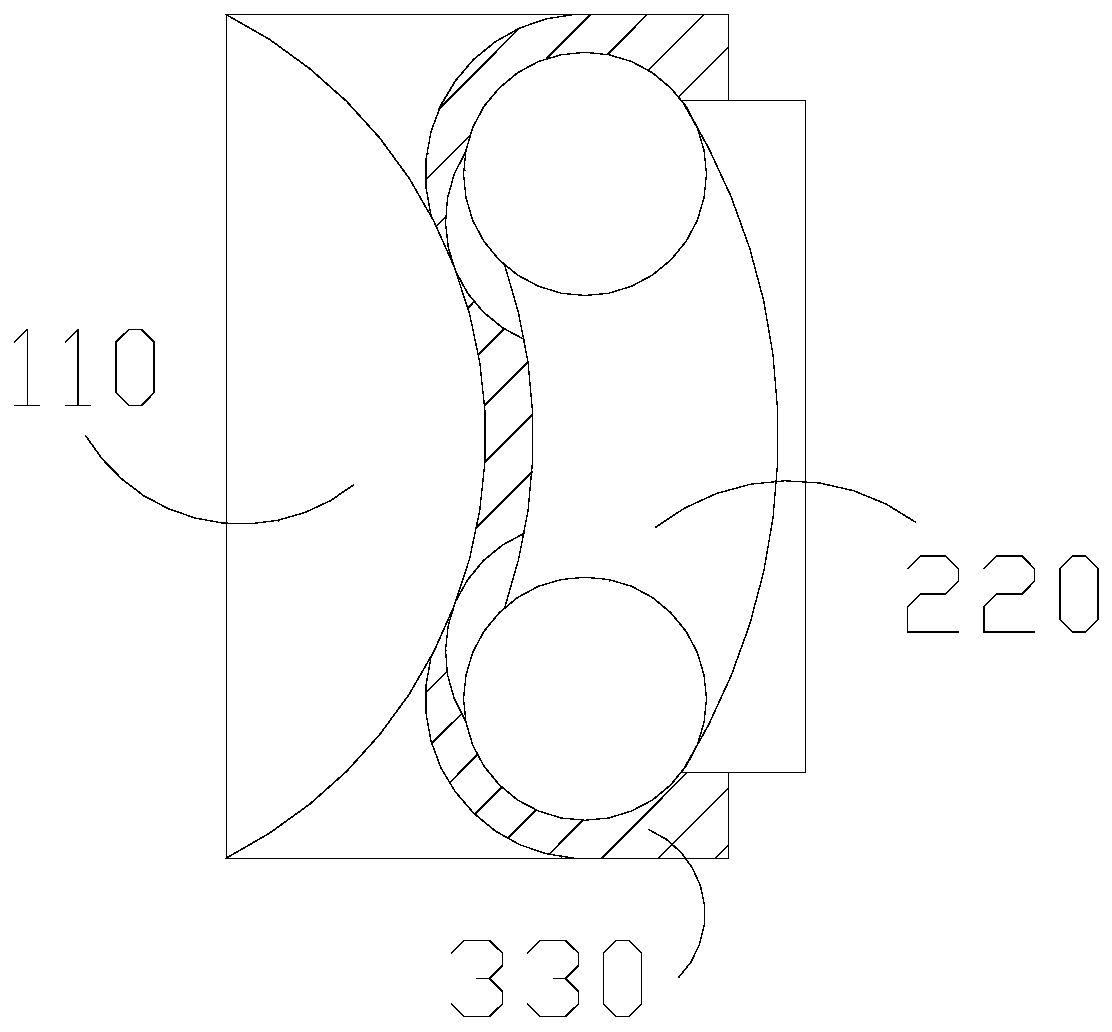
[0042]Wherein, the pressing angle m22 includes the front rubber head 01, the septum ball 02, and the rear corner 03, the septum ball 02 is against the outer surface of the rear corner 03, and the septum ball 02 is far away from the rear corner 03 One end is connected with the front rubber head 01, the septum ball 02 is made of rubber material, which has a certain cushioning effect, the front rubber head 01 changes with the change of the outer layer resistance, and the back support angle 03 To stabilize the connecting part, the septum ball 02 is placed between the fixed part and the stressed part to play a buffering role.
[0043] Wherein, the front rubber head 01 includes a clip s10, a middle support angle s20, an extension layer s30, and a hook s40. The middle support angle s20 is installed on the outer surface of the hook s40, and the middle support angle s20 is attached to With the upper and lower ends of the clip...
PUM
 Abstract
Description
Claims
Application Information
 - R&D Engineer
- R&D Manager
- IP Professional
- Industry Leading Data Capabilities
- Powerful AI technology
- Patent DNA Extraction
Browse by: Latest US Patents, China's latest patents, Technical Efficacy Thesaurus, Application Domain, Technology Topic, Popular Technical Reports.
© 2024 PatSnap. All rights reserved.Legal|Privacy policy|Modern Slavery Act Transparency Statement|Sitemap|About US| Contact US: help@patsnap.com