Hardware drilling equipment

A drilling equipment and hardware technology, applied in the hardware field, can solve the problems of drilling head and objects damage, rigid slippage, etc., and achieve the effect of preventing displacement

Active Publication Date: 2020-07-28
永州市迈锐客科技有限公司
View PDF5 Cites 0 Cited by
  • Summary
  • Abstract
  • Description
  • Claims
  • Application Information

AI Technical Summary

Problems solved by technology

[0006] In order to solve the above-mentioned technology, when the small hardware parts are in the shape of a sphere, the drilling head of the equipment is pressed against the apex of the sphere-shaped part. When drilling, due to the small force-bearing area with the object, it is easier to cause rigid slippage, resulting in drilling The problem of damage to holes and objects

Method used


Image

  • Hardware drilling equipment
  • Hardware drilling equipment
  • Hardware drilling equipment

Examples


Embodiment 1

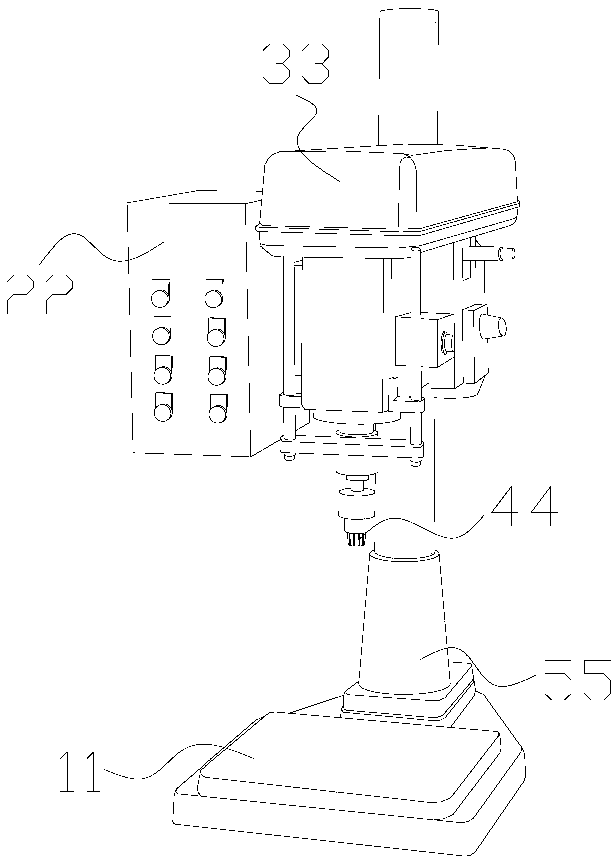
[0031] as attached figure 1 to attach Figure 5 Shown:

[0032] The present invention provides a hardware drilling device, the structure of which includes a workbench 11 , a console 22 , an implementing end 33 , a drilling head 44 , and a support rod 55 .

[0033] The upper surface of the workbench 11 is vertically welded with a support rod 55, and the end of the support rod 55 away from the workbench 11 is connected to the implementation end 33, and the lower end of the implementation end 33 is penetrated with a drilling head 44. The console 22 It is welded to the side surface of the implementation end 33.

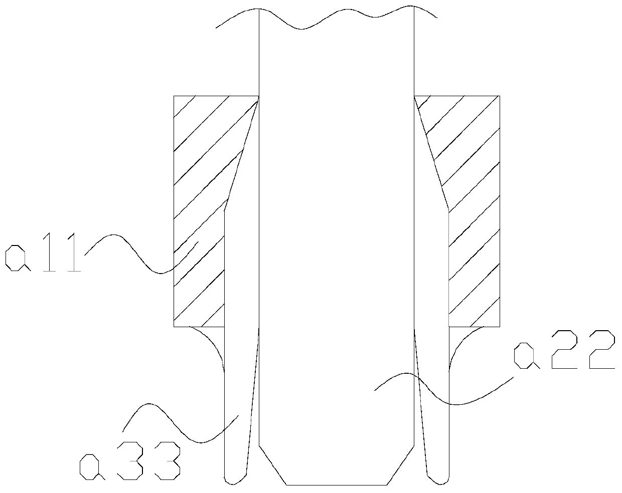
[0034] Wherein, the drilling head 44 includes an outer limiting shell a11, a drill body a22, and a supporting edge a33. The supporting edge a33 is against the outer surface of the drill body a22. The inner wall of the limit case a11, the support edge a33 evenly surrounds the outer surface of the drill body a22, the outer limit case a11 limits the overall expansion and ...

Embodiment 2

[0041] as attached Figure 6 to attach Figure 8 Shown:

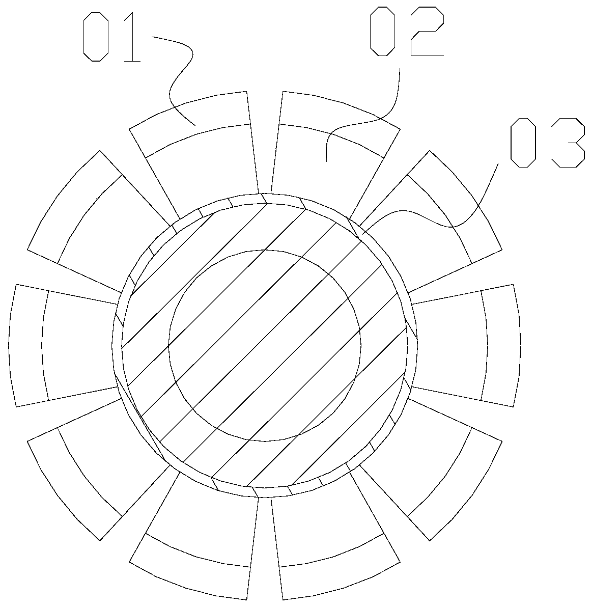
[0042] Wherein, the swing angle w22 includes a spacer e1, a force core e2, and an outer covering layer e3, the outer covering layer e3 is attached to the outer surface of the force core e2, and spacers are installed between the force cores e2 The strip e1, the force core e2 has a triangular structure and is evenly distributed in a fan shape, and the spacers e1 evenly space the active parts, and the force core e2 follows the arc required by the outer layer for bending and stretching.

[0043] Wherein, the force core e2 includes a return-shaped core m21 and an open angle m22. The return-shaped core m21 is against the outer surface of the open angle m22. The return-shaped core m21 is made of soft rubber material and has a certain degree of extrusion. Compression and resilience, the opening angle m22 bears the force on both sides and presses towards the middle, and the return-shaped core m21 gives the outer layer a certai...


PUM


Abstract

The invention discloses hardware drilling equipment. The hardware drilling equipment structurally comprises a working table, a control table, an implementation end, a drilling head and a supporting rod, the supporting rod is vertically welded to the upper surface of the working table, and the end, away from the working table, of the supporting rod is connected with the implementation end. The hardware drilling equipment has the following beneficial effects that the implementation end drives the drilling head to vertically move downwards, the supporting edge of the drilling head can move downwards along the periphery of a hole site, a stress layer is protected by a force isolation layer, and when a drill body processes a hardware ball body, the peripheral part of the drill hole can be fixedand prevented from moving; and the force of an outer wrapping layer can be borne by a force following core to be combined to a certain extent, and bending and stretching are carried out according tothe radian needed by the outer layer, so that a main pocket body bears external force in a large area, when two hard cores are stressed to be bent, a counter-force effect is achieved, the force following core can be bent tightly, the force following core can change along with the radian when wrapping the edge of the ball body, and wrapping is pushed by the counter force.

Description

technical field [0001] The invention belongs to the field of hardware, and more specifically relates to a hardware drilling device. Background technique [0002] There are many uses for small hardware parts. Some assembly methods require drilling. When drilling, fix the hardware and let the equipment apply force from top to bottom. Within a fixed range, carry out Drilling process, after leaving the hardware, the drilling is successful. [0003] Based on the inventor's discovery above, existing hardware drilling machines mainly have the following deficiencies, such as: [0004] When the small hardware parts are in the shape of a sphere, the drilling head of the equipment is against the apex of the sphere-shaped part. When drilling, due to the small force-bearing area with the object, it is easy to cause rigid slippage, resulting in the drilling head and the object. damage. [0005] Therefore need to propose a kind of hardware drilling equipment. Contents of the invention...

Claims


Application Information

Patent Timeline
Patent Type & Authority Applications(China)
IPC IPC(8): B23B41/00B23B47/00B23Q3/00
CPCB23B41/00B23B47/00B23Q3/00B23Q2703/10
Inventor 李溪坂
Owner 永州市迈锐客科技有限公司
Why Eureka
Try Eureka