Fuel conveying system with drying device

A fuel delivery and drying device technology, applied in the direction of fuel, solid fuel, biofuel, etc., can solve the problems that affect the combustion calorific value of the mixture of sludge and coal ash, and affect the power generation efficiency of thermal power plants, so as to ensure the combustion calorific value and improve drying efficiency effect

Inactive Publication Date: 2020-07-03
杭州航民江东热电有限公司
View PDF9 Cites 0 Cited by
  • Summary
  • Abstract
  • Description
  • Claims
  • Application Information

AI Technical Summary

Problems solved by technology

[0004] The above existing technical solutions have the following defects: the sludge and coal ash are dried by the drying device when they are transported in the cage, and the mixture of sludge and coal ash is bonded and solidified in the cage according to the different components contained in the sludge. Or both are in powder form, and in order to ensure that the sludge and coal ash have a higher calorific value after mixing, the ratio is usually set when mixing the sludge and coal ash. In the above technical scheme, the dried coal ash and sewage It is difficult to ensure that the mixture of sludge enters the furnace and maintains a good ratio, which will affect the combustion calorific value of the mixture of sludge and coal ash, which will inevitably affect the power generation efficiency of the thermal power plant

Method used


Image

  • Fuel conveying system with drying device
  • Fuel conveying system with drying device
  • Fuel conveying system with drying device

Examples


Embodiment Construction

[0039] The present invention will be described in further detail below in conjunction with the accompanying drawings.

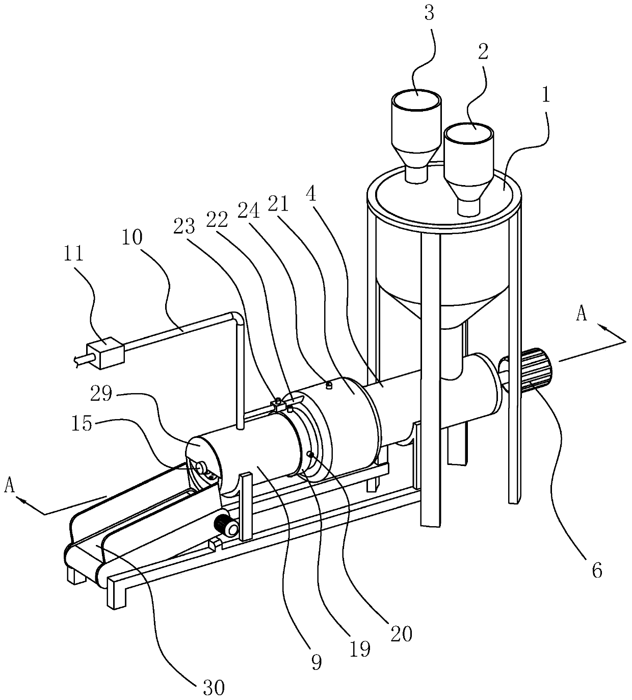
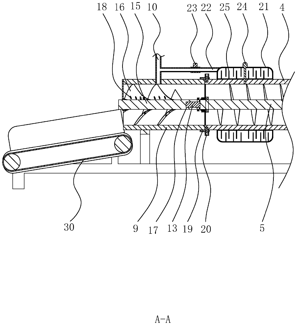
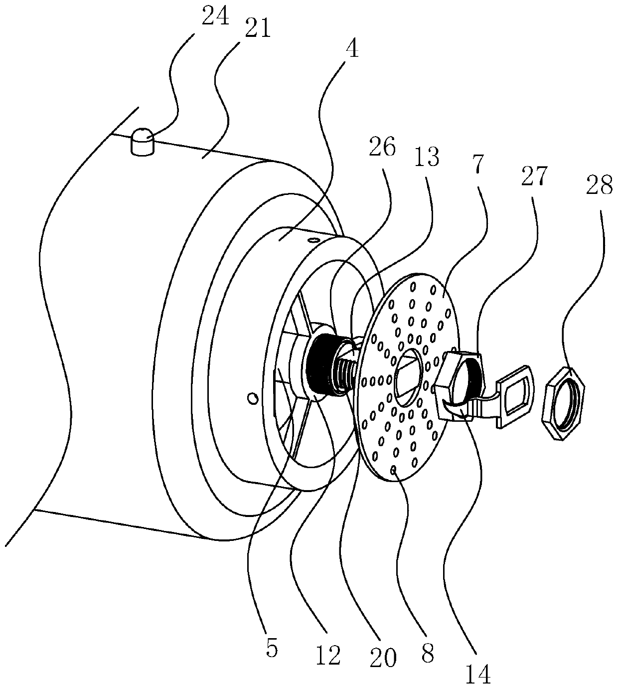
[0040] refer to figure 1 and figure 2 , is a fuel delivery system with a drying device disclosed in the present invention, including a feeding device, a mixing tank 1, a material extruding device, a drying device and a transmission device 30; the feeding device includes a container for holding pulverized coal and sludge The pulverized coal hopper 2 and the sludge hopper 3, the pulverized coal hopper 2 and the sludge hopper 3 are arranged directly above the mixing tank 1 and the outlets of both extend into the material inlet of the mixing tank 1; the extruding device includes a horizontal setting And the material cylinder 4 whose material inlet is connected with the material outlet of the mixing tank 1, the coaxial rotation in the material cylinder 4 is connected with the auger 5, the end of the material cylinder 4 close to the mixing tank 1 is closed, and t...


PUM


Abstract

The invention relates to a fuel conveying system with a drying device. The fuel conveying system comprises a feeding device, a stirring barrel, a material extruding device, the drying device and a conveying device, wherein the feeding device comprises a coal powder hopper and a sludge hopper; a discharging port of the coal powder hopper and a discharging port of the sludge hopper both extend intoa feeding port of the stirring barrel; the material extruding device comprises a material barrel with the feeding port communicating with the discharging port of the stirring barrel; an auger is coaxially and rotationally connected in the material barrel; one end of the material barrel is closed, and a material extruding plate is arranged at the other end of the material barrel; a plurality of material extruding holes are formed in the material extruding plate; a preheating mechanism is arranged on the peripheral wall of the material barrel; the drying device comprises a drying barrel arrangedat the end, close to the material extruding plate, of the material barrel; a hot air pipe communicates in the drying barrel; and a material overturning mechanism is arranged in the drying barrel. According to the fuel conveying system, a coal powder and sludge mixture is preheated through the preheating mechanism and then extruded into strips from the material extruding plate, drying is conductedthrough the drying barrel, the coal powder and sludge mixture can be conveyed into a hearth to be combusted at a good proportion, and the good combustion heat value of the coal powder and sludge mixture is ensured.

Description

technical field [0001] The invention relates to the technical field of thermoelectric fuel transmission equipment, in particular to a fuel delivery system with a drying device. Background technique [0002] Sludge is a fuel with low calorific value. Combustion of sludge alone is not economical, and at the same time, the discharge of pollutants is also high. However, the mixed combustion of sludge and coal not only uses coal to increase the calorific value of sludge, but also improves the efficiency of sewage. The stability of the mud combustion process, and the alkaline components in the sludge can inhibit the emission of toxic and harmful gases such as nitrogen oxides and sulfur oxides during the coal combustion process. The co-firing of coal and sludge greatly reduces the burden of sludge treatment, and using sludge as fuel also greatly saves energy. [0003] The existing patent notification number is CN207035777U, which proposes a fuel delivery system with a drying devic...

Claims


Application Information

Patent Timeline
IPC IPC(8): F23K3/00F23K1/00C10L5/46C10L5/04C10L5/06
CPCC10L5/04C10L5/06C10L5/46F23K1/00F23K3/00Y02E50/10Y02E50/30
Inventor 吴关兴
Owner 杭州航民江东热电有限公司
Why Eureka
Try Eureka