Pneumatic Tire

a pneumatic tire and tire body technology, applied in the field of pneumatic tires, can solve the problems of reduced rigidity and difficulty in sufficiently maintaining handling stability performance (dry handling stability), and achieve the effects of reducing tire weight and rolling resistance, increasing rigidity of the sidewall portion on the vehicle outer side, and maintaining dry handling stability at a high degr

Active Publication Date: 2018-08-09
YOKOHAMA RUBBER CO LTD
View PDF10 Cites 1 Cited by
  • Summary
  • Abstract
  • Description
  • Claims
  • Application Information

AI Technical Summary

Benefits of technology

[0009]In the present technology, a partial tie rubber layer is used, and therefore, tire weight and rolling resistance can be reduced as compared to a conventional pneumatic tire having a full tie rubber layer. At this time, rubber thickness (first technology), periphery length (second technology), and rubber hardness (third technology) vary for an inner tie rubber layer disposed on a vehicle inner side and an outer tie rubber layer disposed on a vehicle outer side, and increase on the outer tie rubber layer more than the inner tie rubber layer, and therefore, the rigidity of a sidewall portion on the vehicle outer side can be increased, and dry handling stability can be maintained at a high degree.
[0010]The first technology, second technology, and third technology can be combined with each other. In other words, in the first technology (when setting the rubber thickness), a periphery length x1 of an inner tie rubber layer differs from a periphery length x2 of an outer tie rubber layer, and a difference Δx between the periphery length x2 of the outer tie rubber layer and the periphery length x1 of the inner tie rubber layer is 5 mm or greater and 0.25 times or less a periphery length X of a tire inner surface from a bead toe to a tire equator. Thereby, the rigidity of the sidewall portion on the vehicle outer side can be further enhanced, which is advantageous in enhancing dry handling stability. Note that in the present technology, “periphery length” refers to a length measured along an extension direction of tire components (outer tie rubber layer, inner tie rubber layer, tire inner surface) in a tire meridian cross section.
[0011]Furthermore, in the first technology (when setting the rubber thickness) or second technology (when setting the periphery length), a rubber hardness h1 of an inner tie rubber layer differs from a rubber hardness h2 of an outer tie rubber layer, and the rubber hardness h2 of the outer tie rubber layer is preferably from 105% to 150% of the rubber hardness h1 of the inner tie rubber layer. Thereby, the rigidity of the sidewall portion on the vehicle outer side can be further enhanced, which is advantageous in enhancing dry handling stability. Note that “rubber hardness” in the present technology refers to a hardness (referred to as JIS-A hardness) measured at 23° C. by a type A durometer in accordance with JIS (Japanese Industrial Standard) K 6253.

Problems solved by technology

However, simply removing a portion of the full tie rubber layer to achieve a partial tie rubber layer has problems where rigidity is reduced as compared to a conventional tire using a full tie rubber layer, and thus sufficiently maintaining handling stability performance (dry handling stability) is difficult.

Method used


Image

  • Pneumatic Tire
  • Pneumatic Tire
  • Pneumatic Tire

Examples


examples

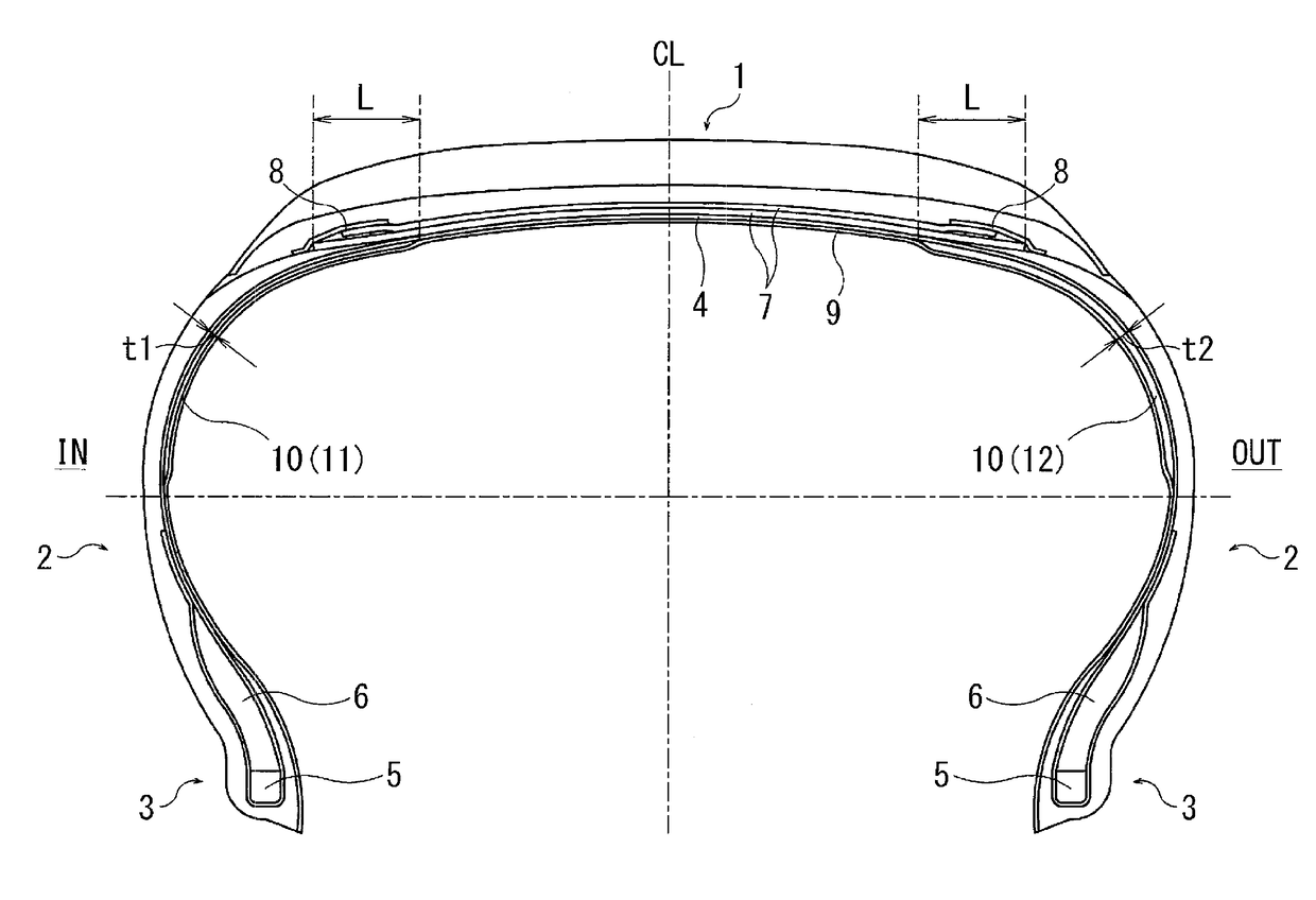
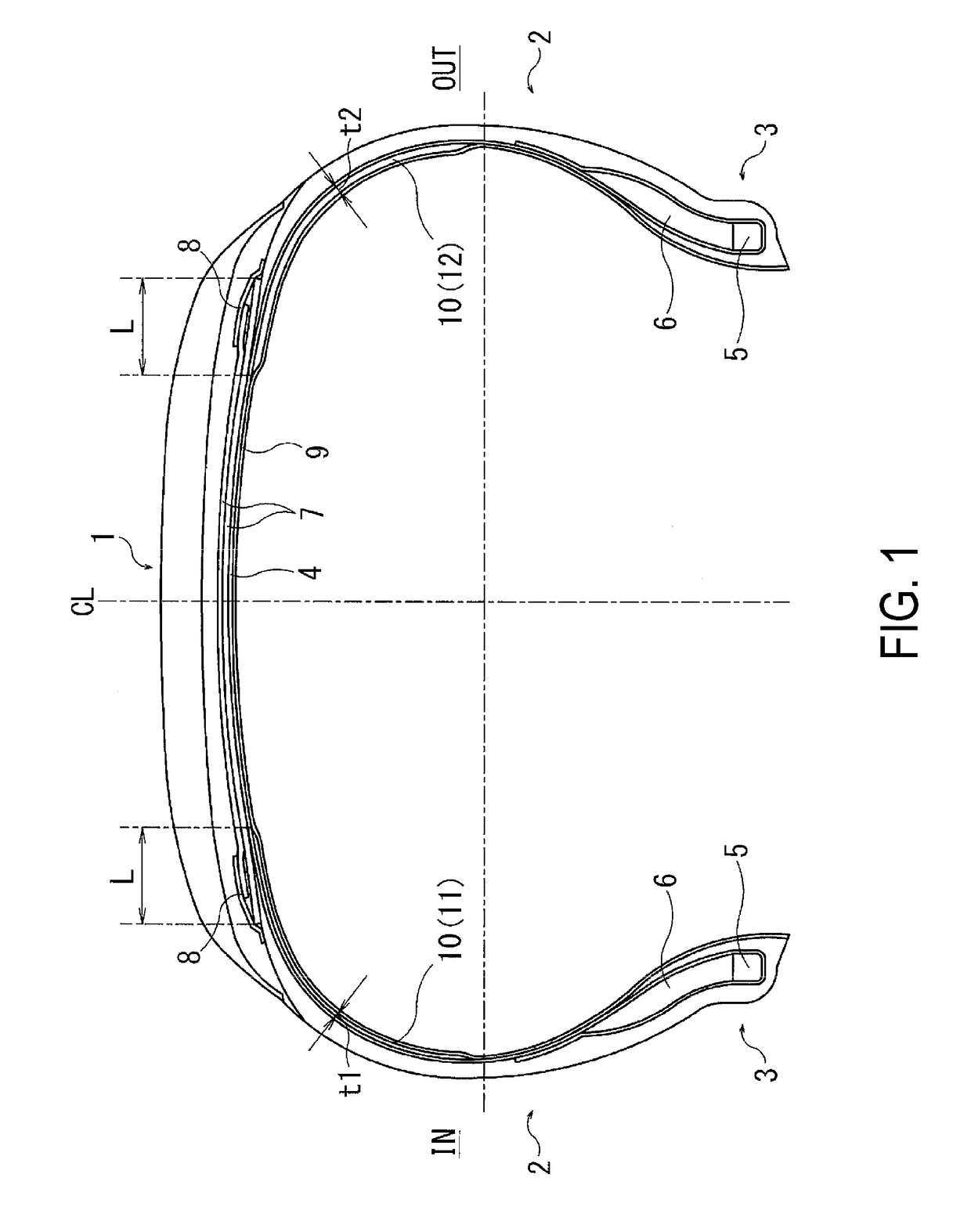
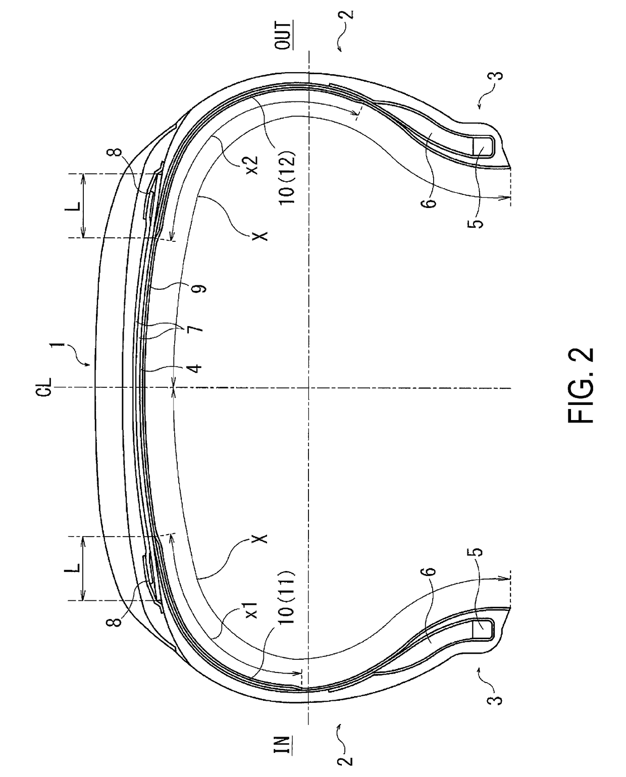
[0033]45 types of pneumatic tires of Conventional Example 1, Comparative Examples 1 to 7, and Examples 1 to 37 were prepared, having a tire size of 195 / 65 R15, having the basic structure common to FIGS. 1 to 4, and for a partial tie rubber layer, the following were set as shown in Tables 1 to 3: rubber thickness t1 of an inner tie rubber layer; rubber thickness t2 of an outer tie rubber layer; ratio (t2 / t1×100) of the rubber thickness t2 with regard to the rubber thickness t1; periphery length x1 of the inner tie rubber layer; periphery length x2 of the outer tie rubber layer; difference Δx between the periphery length x1 of the inner tie rubber layer and periphery length x2 of the outer tie rubber layer; ratio of the difference Δx of the periphery length with regard to a periphery length X of a tire inner surface from a bead toe to a tire equator; rubber hardness h1 of the inner tie rubber layer; rubber hardness h2 of the outer tie rubber layer; and ratio of the rubber hardness h2 ...


PUM


Abstract

A pneumatic tire is provided in which an inner tie rubber layer and an outer tie rubber layer are selectively disposed between a carcass layer and an innerliner layer in a region on both sides in a tire width direction excluding a center region of a tread portion. End portions of the inner tie rubber layer and outer tie rubber layer on a tire equator side are disposed within a range of from 10 mm to 25 mm on an inner side in the tire width direction from an end portion on an outermost side in the tire width direction of a belt layer. A rubber thickness t1 of the inner tie rubber layer differs from a rubber thickness t2 of the outer tie rubber layer. A rubber thickness of the outer tie rubber layer is from 120% to 200% a rubber thickness of the inner tie rubber layer.

Description

TECHNICAL FIELD[0001]The present technology relates to a pneumatic tire provided with a partial tie rubber layer selectively disposed on a portion between a carcass layer and innerliner layer, and particularly relates to a pneumatic tire capable of reducing tire weight and rolling resistance while maintaining handling stability on a dry road surface.BACKGROUND ART[0002]In general, for a pneumatic tire, when an unvulcanized tire is inflated when manufacturing a tire, a tie rubber layer is disposed between a carcass layer and innerliner layer in order to prevent a carcass cord from biting into the innerliner layer.[0003]In recent years, for this tie rubber layer, using a partial tie rubber layer selectively disposed on a portion and not an entire region between the carcass layer and innerliner layer has been proposed in order to achieve a reduction in tire weight and rolling resistance (for example, refer to Japan Patent No. 5239507). This partial tie rubber layer is disposed on at le...

Claims


Application Information

Patent Timeline
Patent Type & Authority Applications(United States)
IPC IPC(8): B60C5/14B60C3/06
CPCB60C5/14B60C3/06B60C2005/145B60C5/142B60C2009/145Y02T10/86B60C1/0008B60C9/02
Inventor SUZUKI, TAKAHIRO
Owner YOKOHAMA RUBBER CO LTD
Why Eureka
Try Eureka