Bridge pile foundation concrete pouring equipment and process applied to water accumulated area
A concrete and pile foundation technology, which is applied to clay preparation devices, infrastructure engineering, cement mixing devices, etc., can solve the problems of cumbersome construction, time-consuming construction, large material discharge resistance, and long process time, so as to avoid concrete spillage and avoid cracked effect
- Summary
- Abstract
- Description
- Claims
- Application Information
AI Technical Summary
Problems solved by technology
Method used
Image
Examples
Embodiment 1
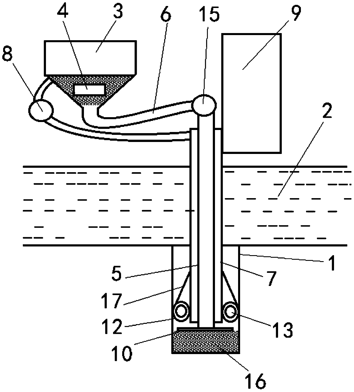
[0022] according to figure 1 , a bridge pile foundation concrete 16 pouring equipment applied to the water accumulation area, which mainly includes: a mixing hopper 3, the mixing hopper 3 is fixedly arranged above the water surface in the area of the foundation pit 1, and the mixing hopper 3 is provided with a stirring Mechanism 4; filling pipe 5, the filling pipe 5 is a rigid vertical pipe, the top of the filling pipe 5 communicates with the bottom of the mixing hopper 3 through the high-pressure hose 6; recovery pipe 7, the recovery pipe 7 is nested It is arranged outside the filling pipe 5, and the top of the recovery pipe 7 is in sealing connection with the outer wall of the filling pipe 5, and the top of the recovery pipe 7 communicates with the inside of the mixing hopper 3 through the suction pump 8; the lifting mechanism 9, The lifting mechanism 9 is fixedly arranged above the foundation pit 1 and cooperates with the outer wall of the recovery pipe 7 to move the reco...
Embodiment 2
[0025] The bottom of the pouring pipe 5 is provided with a water retaining sheet extending horizontally around; the outer edge of the water retaining sheet is provided with a cover edge bent downward.
[0026] In the above arrangement, the water retaining sheet 10 is used to isolate the concrete 16 in the foundation pit 1 from contacting the water body 2, so as to avoid dilution and waste caused by mutual penetration between the two. The edge of the cover guides the poured concrete 16 to prevent the poured concrete 16 from flowing upwards, and at the same time reduces the scraping between the water retaining sheet 10 and the inner wall of the foundation pit 1 during the upward pulling of the recovery pipe 7, and the low resistance At the same time, it also plays the role of axis positioning.
Embodiment 3
[0028] The outer wall of the bottom end of the recovery pipe 7 is provided with a flexible sleeve 12 in the circumferential direction, and the top of the flexible sleeve 12 is connected to the top of the recovery pipe 7 through a traction sleeve 17; the flexible sleeve 12 is provided with an annular expansion body.
[0029] In the above arrangement, the flexible sleeve 12 can be closely attached to the inner wall of the foundation pit 1 through the expansion body, and forms a seal between the recovery pipe 7 and the inner wall of the foundation pit 1 to avoid overflow of the concrete 16 or seepage of the water body 2 . At the same time, when the recovery pipe 7 is lifted, the traction cylinder 17 pulls the flexible sleeve 12 upwards, so that the outer wall of the flexible sleeve 12 is exerted pulling force while cooperating with the recovery pipe 7, so as to avoid the rupture of the flexible sleeve 12.
PUM
 Abstract
Description
Claims
Application Information
 - R&D Engineer
- R&D Manager
- IP Professional
- Industry Leading Data Capabilities
- Powerful AI technology
- Patent DNA Extraction
Browse by: Latest US Patents, China's latest patents, Technical Efficacy Thesaurus, Application Domain, Technology Topic, Popular Technical Reports.
© 2024 PatSnap. All rights reserved.Legal|Privacy policy|Modern Slavery Act Transparency Statement|Sitemap|About US| Contact US: help@patsnap.com


