Electrical contact assembly with groove

A technology of electrical contacts and components, applied in the direction of contact electrical connection, contact shell/screen, contact surface shape/structure, etc., can solve the problems of low yield, easy solder climbing points, etc., and achieve large charging volume Effect

Pending Publication Date: 2020-06-30
ZHEJIANG FUDA ALLOY MATERIALS TECH CO LTD
View PDF0 Cites 1 Cited by
  • Summary
  • Abstract
  • Description
  • Claims
  • Application Information

AI Technical Summary

Problems solved by technology

[0004] The purpose of the present invention is to provide an electrical contact assembly that prevents solder from creeping up when the electrical contact is welded, and solves the problems of the solder of the electrical contact being prone to creeping up and low yield in the prior art

Method used


Image

  • Electrical contact assembly with groove
  • Electrical contact assembly with groove
  • Electrical contact assembly with groove

Examples


Embodiment 1

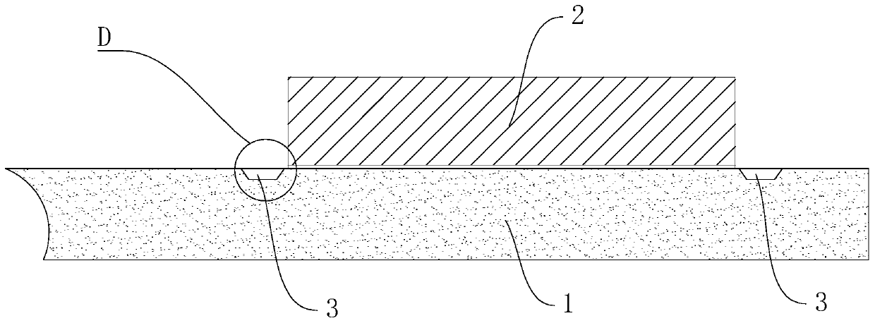
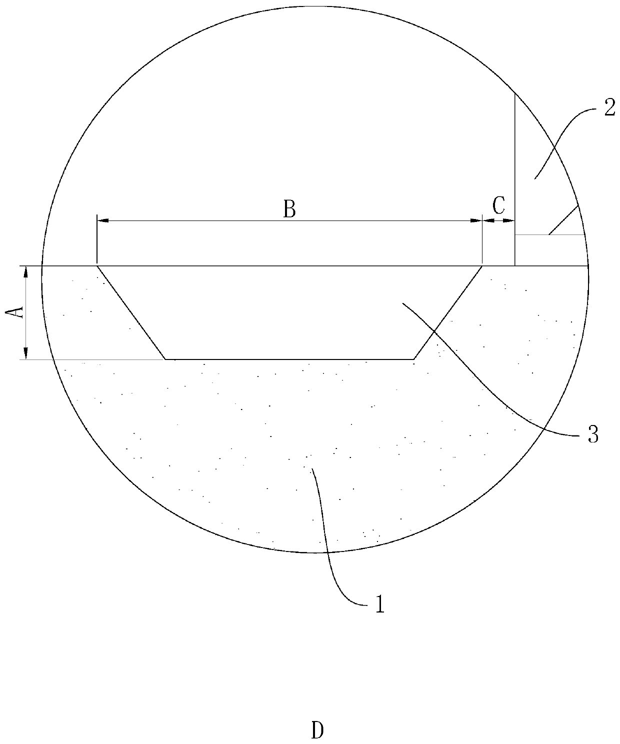
[0026] refer to Figure 1 to Figure 3 , a grooved electrical contact assembly, including a contact bridge 1 and an electrical contact 2 placed on the contact bridge 1, a groove 3 is opened on the side of the contact bridge 1 facing the electrical contact 2, and the groove 3 is arranged near the The intersection between the contact bridge 1 and the electrical contact 2; the groove 3 is arranged around the outer circumference of the electrical contact 2 to form a ring shape, and the shape of the groove 3 is adapted to the outer peripheral shape of the electrical contact 2 . The cross-sectional shape of the groove 3 includes a trapezoid, specifically an isosceles trapezoid, the lower base of the isosceles trapezoid is set upward and the inclination angle is 60°.

[0027] The distance between the groove 3 and the electrical contact 2 is 0-0.5mm, preferably 0.1mm (the letter C is used in the figure to indicate the distance between the groove 3 and the electrical contact 2); the de...

Embodiment 2

[0030] refer to Figure 4 , The difference between this embodiment and Embodiment 1 is that the apex angles of the isosceles trapezoid are all provided with an arc-shaped excessively arc-shaped surface 5, the A dimension is 0.6mm, the B dimension is 1.5mm, and the C dimension is 0.05mm. The fillet radius of the arc surface 5 is 0.75mm. In this embodiment, the solder is B25AgCuZn solder, and the specification before welding is 4x6x0.08mm; the welding method of the solder is high-frequency induction welding, and the welding coil is square, and the coil is heated in the middle of the contact bridge 1 during welding.


PUM

PropertyMeasurementUnit
Depthaaaaaaaaaa
Cross section widthaaaaaaaaaa
Thicknessaaaaaaaaaa

Abstract

The invention discloses an electrical contact assembly with a groove, which comprises a contact bridge and an electrical contact arranged on the contact bridge, the surface of the contact bridge facing the electrical contact is provided with the groove, the groove is arranged close to the intersection of the contact bridge and the electrical contact, and solder formed by welding is filled betweenthe groove and the edge of the electrical contact. The invention has the following advantages and effects: the design mode breaks through the conventional design thought of the existing electrical contact element, the change of the structure of the contact bridge product is adopted to limit the solder from climbing to the working surface of the electrical contact, and extra cost is not required tobe increased. The whole structure is easy to machine, accurate, effective and high in efficiency, and the finished product rate of products is increased.

Description

technical field [0001] The invention relates to the field of low-voltage electrical appliances, in particular to an electrical contact assembly with grooves. Background technique [0002] At present, the parts manufacturing of low-voltage electrical appliances is constantly developing towards componentization and integration. Among them, the most critical "heart" component of low-voltage electrical appliances is the electrical contact assembly, so how to ensure the welding quality and Stability has become the key to determine the quality of low-voltage electrical products. [0003] The existing electrical contact assembly includes an electrical contact 2 and a contact bridge 1 (refer to Figure 5 ), at present, when the electrical contact suppliers are performing the welding process between the electrical contact and the contact bridge, they first place the solder and the electrical contact on the contact bridge in turn to make the three complete the docking, and then perfor...

Claims


Application Information

Patent Timeline
IPC IPC(8): H01H1/06H01H1/58H01H1/64
CPCH01H1/06H01H1/58H01H1/64
Inventor 何斌沈冬月龚志杰余小年申志刚叶志锋黄庆忠张明江陈松杨
Owner ZHEJIANG FUDA ALLOY MATERIALS TECH CO LTD
Why Eureka
Try Eureka