
Underwater optical positioning algorithm applied to pressure vessel

A technology of optical positioning and pressure vessels, which is applied in the direction of instruments, calculations, reactors, etc., to achieve the effect of strong real-time calculation

Active Publication Date: 2020-06-30
RES INST OF NUCLEAR POWER OPERATION +1
View PDF5 Cites 0 Cited by
  • Summary
  • Abstract
  • Description
  • Claims
  • Application Information

AI Technical Summary

Problems solved by technology

If these welds are damaged, there is a greater risk of continued use under high temperature and pressure

Method used


Image

  • Underwater optical positioning algorithm applied to pressure vessel
  • Underwater optical positioning algorithm applied to pressure vessel
  • Underwater optical positioning algorithm applied to pressure vessel

Examples


Embodiment Construction

[0024] Below in conjunction with accompanying drawing and specific embodiment this patent is described in detail:

[0025] The present invention will be described in further detail below in conjunction with the accompanying drawings and specific embodiments.

[0026] An underwater ROV optical positioning algorithm applied to a pressure vessel environment, comprising the following steps:

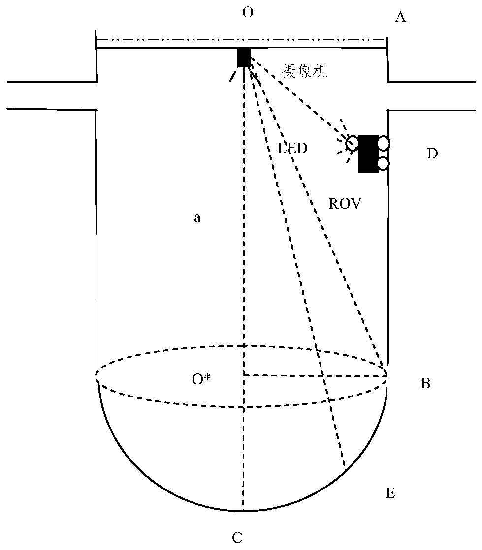
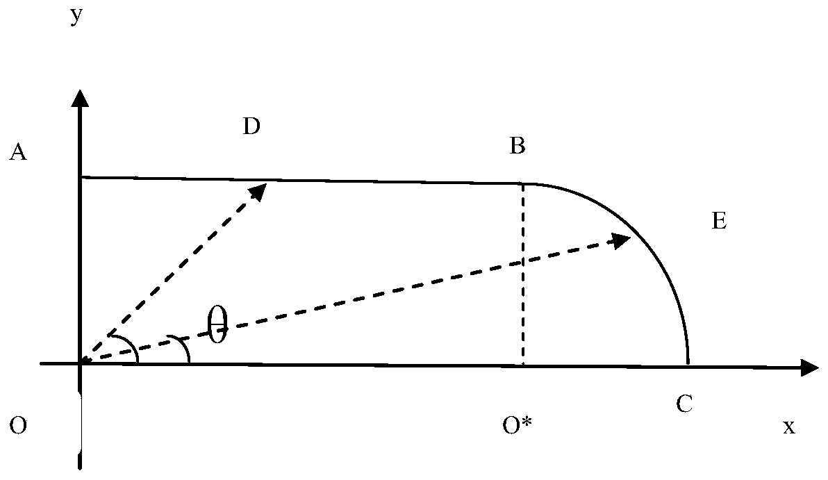
[0027] For shapes like figure 2 For the pressure vessel, use the relevant knowledge of analytic geometry to establish the relationship between the variable θ and the depth x, see image 3 .

[0028] Taking O as the coordinate origin, OC as the x-axis, and OA as the y-axis, establish a rectangular coordinate system Oxy, then the following points and their coordinates are as follows: O(0,0), O*(a,0), A(0, r), B(a,r), C(a+r,0). If the abscissa of point D between AB is x, ∠COD=θ, then If the abscissa of point E on the arc BC is x, the ordinate is y, and ∠COE=θ, then at the same time: and...


PUM


Abstract

The invention belongs to an underwater positioning technology, and particularly relates to an underwater optical positioning algorithm applied to a pressure vessel environment. Under the existing detection condition, the ROV can be possibly guided to a specified position only when the underwater ROV is positioned. The method comprises the following steps: step 1, inputting a bus length a and radius data r of a pressure vessel, a vertical field angle A of a camera and a target surface height B of a CCD of the camera; 2, solving a critical angle; 3, calculating an angle theta 0 corresponding tothe unit radial length of the image plane of the camera; 4, turning on an LED lamp on the ROV; 5, according to the principle from large to small, adjusting the pitch angle alpha of the camera installed in the center of the remote control platform till the bright spot enters the center line of the view field of the camera, wherein the rotation angle at the moment is the azimuth angle of the ROV; and step 6, recording a bright spot position (0, y0), and solving a central variable; and step 7, calculating the depth x of the ROV. By using the method, the position of the ROV of the submersible vehicle can be obtained by using the LED lamp on the ROV under the assistance of the camera.

Description

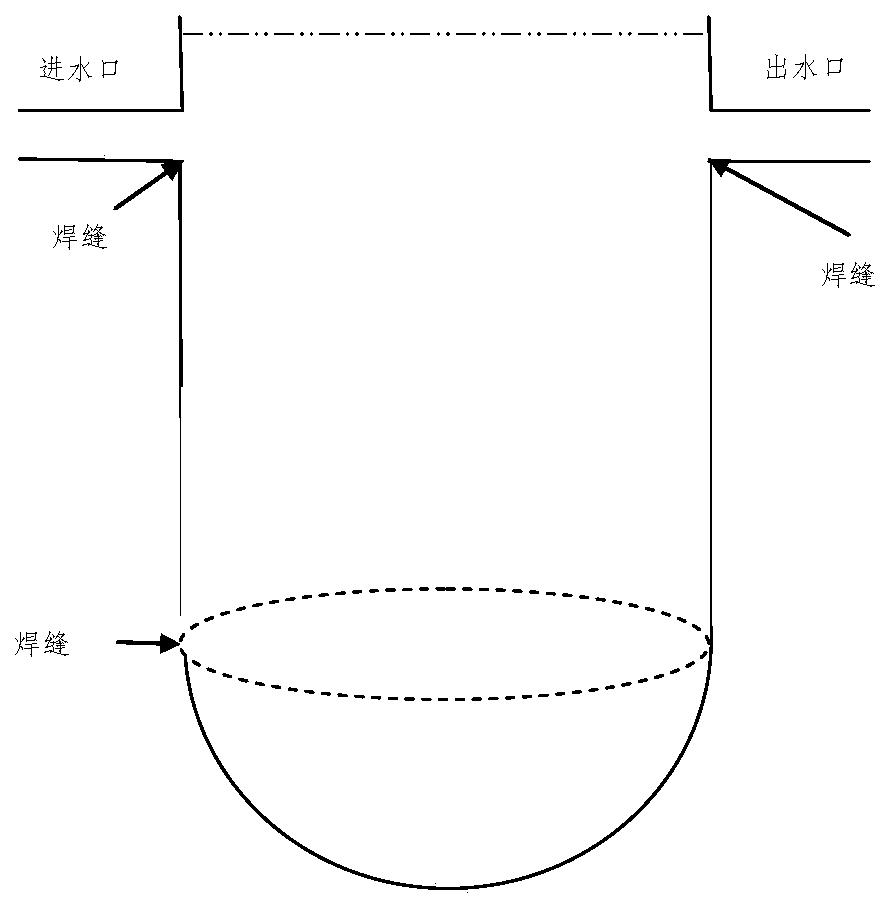
technical field [0001] The invention belongs to underwater positioning technology, and in particular relates to an underwater optical positioning algorithm applied to a pressure vessel environment. Background technique [0002] A nuclear reactor pressure vessel is usually composed of an upper cylinder and a lower hemisphere, and there are water inlets and outlets on the side of the cylinder. figure 1 A cross-sectional schematic diagram of a nuclear reactor pressure vessel. There are welds in the pressure vessel at the water outlet, water inlet, the junction of the cylinder and the bottom hemisphere, and some other specific positions. If these welds are damaged, there is a greater risk of continued use under high temperature and pressure. Therefore, regular testing and maintenance of pressure vessels is required. Usually the underwater remotely controlled submersible vehicle (ROV) must perform ultrasonic inspection on the weld at a designated position to check for damage d...

Claims


Application Information

Patent Timeline
Patent Type & Authority Applications(China)
IPC IPC(8): G06T7/70G01C11/00G21C17/01G21C17/013
CPCG06T7/70G01C11/00G21C17/01G21C17/013G06T2207/10004Y02E30/30
Inventor 陈姝魏文斌张志义冯美名张益成
Owner RES INST OF NUCLEAR POWER OPERATION
Learn More