
Wellhead stabilizing device for ocean drilling construction

A stabilizing device, marine technology, applied in earth-moving drilling, wellbore/well components, sealing/packing, etc., can solve the problems of long time for conduit injection and waiting for conduit to be stabilized, high construction cost, and high conduit cost

Pending Publication Date: 2020-06-30
EXPLORATION TECH RES INST OF CHINESE ACADEMY OF GEOLOGICAL SCI
View PDF0 Cites 2 Cited by
  • Summary
  • Abstract
  • Description
  • Claims
  • Application Information

AI Technical Summary

Problems solved by technology

The traditional wellhead stabilization device has the following defects: 1. It cannot guarantee the levelness of the wellhead base plate and the verticality of the conduit, so that the verticality of the wellhead head cannot be guaranteed within 1°; 2. It takes a long time for the conduit to spray and wait for the conduit to stabilize. The cost of offshore construction is high; 3. When a deep conduit needs to be lowered, the cost of the conduit is high. If a directional well or a horizontal well is drilled, the vertical section is longer and the kickoff point is at a deeper position, which is not conducive to the exploitation of shallow oil and gas resources.

Method used


Image

  • Wellhead stabilizing device for ocean drilling construction
  • Wellhead stabilizing device for ocean drilling construction
  • Wellhead stabilizing device for ocean drilling construction

Examples


Embodiment Construction

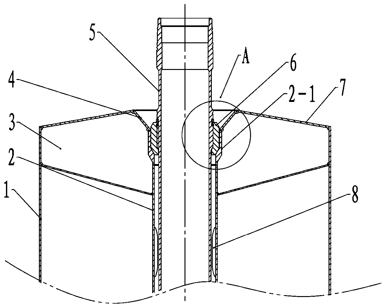
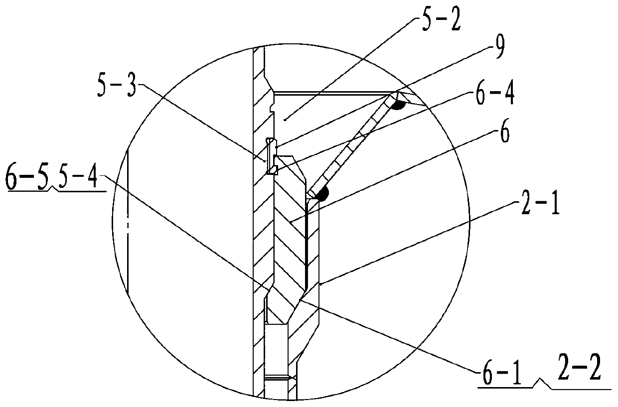
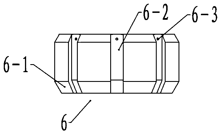
[0022] see figure 1 , Figure 5 and Figure 6 , the present invention includes a suction anchor and a conduit 5. The suction anchor consists of an inner tube 2 and an outer tube 1 to form a double-layer cylinder structure, and the conduit is located in the inner tube. Several ribs 3 are evenly distributed on the upper part of the suction anchor. The ribs are trapezoidal plates. The tubes are welded to improve the stability of the suction anchor and the connection strength of the inner and outer tubes. The annular area between the outer tube and the top of the inner tube is closed by the top plate 7, which is a conical surface to improve the pressure resistance. The top of the inner tube is provided with a transition bell mouth 4, the upper edge of the transition bell mouth is welded with the top plate, and the transition bell mouth is lower. The edge is welded to the top of the upper seat ring. The conduit 5 is a tubular structure, and the thick part at the top of the cond...


PUM


Abstract

A wellhead stabilizing device for ocean drilling construction comprises a suction anchor, a guide pipe and a guide pipe seat, and the upper part of an inner pipe is provided with an upper seat ring; the upper seat ring is an upper column lower taper hole, and the upper part of the guide pipe is provided with a protruding hanging section; the lower part of the hanging section is provided with a hanging section outer truncated cone, and the guide pipe seat is arranged on the hanging section in a sleeving mode; the lower part of the guide pipe seat is provided with a guide pipe seat inner conicalsurface and a guide pipe seat outer truncated cone, and the guide pipe seat outer truncated cone is matched and fit with the guide pipe seat inner conical surface; and the hanging section outer truncated cone is matched and fit with the guide pipe seat inner conical surface. According to the wellhead stabilizing device, the upper seat ring is arranged on the top of the suction anchor, and the guide pipe seat is additionally arranged; the guide pipe is installed in the upper seat ring through the guide pipe seat, and the guide pipe seat and the upper seat ring as well as the guide pipe and theguide pipe seat are coordinated through the conical surfaces; by the aid of the synergistic effect of correcting strips, the concentricity between the guide pipe and a wellhead and the wellhead suction anchor is ensured; and the installation perpendicularity deviation of the suction anchor is controlled within 1 degree, and accordingly the perpendicularity deviation of the suction anchor can be controlled within 1 degree. The wellhead stabilizing device further has the characteristic of easy removal and installation.

Description

technical field [0001] The invention relates to a construction device used in ocean drilling engineering, in particular to a wellhead stabilizing device for ocean drilling construction. Background technique [0002] The wellhead stabilization device is widely used in marine engineering, and its function is similar to the rigid short pile, which has the function of supporting and foundation parts for the wellhead. The traditional subsea drilling wellhead stabilization device consists of a conduit (also known as a casing) and a template. The top of the conduit is a wellhead head. Depending on the weight of the wellhead support equipment, it generally requires tens to hundreds of meters of conduit and wellhead template to be supported together. The weight of the wellhead. The conduit is lowered below the seabed mud surface by jet drilling. The conduit needs to be hoisted by the platform or drilling ship for a period of time to wait for the formation to hold the conduit tightly ...

Claims


Application Information

Patent Timeline
Patent Type & Authority Applications(China)
IPC IPC(8): E21B33/035E21B33/043
CPCE21B33/035E21B33/043
Inventor 牛庆磊邵玉涛崔淑英宋刚于好善刘广韩泽龙赵明韦海瑞陈根龙陈晓君张化民史兵言王兴无贾炜董巍
Owner EXPLORATION TECH RES INST OF CHINESE ACADEMY OF GEOLOGICAL SCI
Learn More