
Hydrogen fuel battery pack of fuel battery vehicle and radiator

A fuel cell stack, fuel cell technology, applied in the direction of fuel cell heat exchange, fuel cell, fuel cell additives, etc., can solve the problems of electric vehicle performance gap, affecting battery life, unsatisfactory, etc., to improve performance and operational safety, increased reliability and consistency, and reduced waste

Inactive Publication Date: 2020-06-26
李得波
View PDF0 Cites 2 Cited by
  • Summary
  • Abstract
  • Description
  • Claims
  • Application Information

AI Technical Summary

Problems solved by technology

[0003] Fuel cell is considered to be one of the top ten technologies that will affect the future world. It is a device that directly converts the chemical energy of fuel (hydrogen, natural gas, liquefied gas, methanol, etc.) into electrical energy. It has the characteristics of high efficiency, low pollution and no noise. , has received widespread attention from all over the world. Recently, fuel cell technology has made breakthroughs and has been applied to automobiles, ships, etc. At present, the core component of fuel cells is proton exchange membranes, and temperature changes have a great impact on proton exchange membranes. Studies have shown that when the fuel cell temperature is between 70°C and 80°C, the water distribution in the membrane can be improved, the proton transfer rate in the membrane can be increased, and the membrane resistance can be reduced, thereby improving the performance of the fuel cell. However, since the fuel cell operates continuously , the chemical reaction continues to output electric energy, and at the same time, a large amount of heat is released, so that the temperature of the fuel cell quickly exceeds this temperature, and the stability and proton conductivity of the battery decrease, resulting in unstable output power of the fuel cell and seriously affecting the battery. lifespan, and may even cause major safety problems. The core of the power battery cooling system is how to maintain the battery as a whole in an appropriate temperature range, and ensure that the temperature of the battery itself and the batteries in the battery pack are uniform. At this stage, the energy density of power batteries is limited, and the power density of battery packs has not yet reached a satisfactory level. Compared with traditional fuel vehicles, there is still a gap in the performance of electric vehicles, which is mainly limited by the cruising range, charging time and battery cycle life. At present, the technical development trend of power batteries is high energy density and long life cycle. The increasing energy density will inevitably increase the temperature of the battery during charging and discharging. Among the various performance factors that affect the life of power batteries, The battery temperature has a great influence. Excessively high battery temperature will increase the irreversible reactants inside the battery, thereby reducing the battery capacity and cycle life. In addition, the uneven temperature distribution inside the battery pack will also cause the gap between the battery cells and the battery module. The unevenness of the performance between them will eventually affect the consistency of battery performance and the accuracy of battery state of charge estimation. Therefore, maintaining proper battery temperature and uniform temperature distribution is crucial to maintaining battery cycle life and charge-discharge performance. Important, and a high-performance battery cooling system will inevitably further increase the size and weight of the battery pack, which is not conducive to the lightweight of electric vehicles, consumes more parasitic power, and further reduces the cruising range

Method used


Image

  • Hydrogen fuel battery pack of fuel battery vehicle and radiator
  • Hydrogen fuel battery pack of fuel battery vehicle and radiator
  • Hydrogen fuel battery pack of fuel battery vehicle and radiator

Examples


Embodiment 1

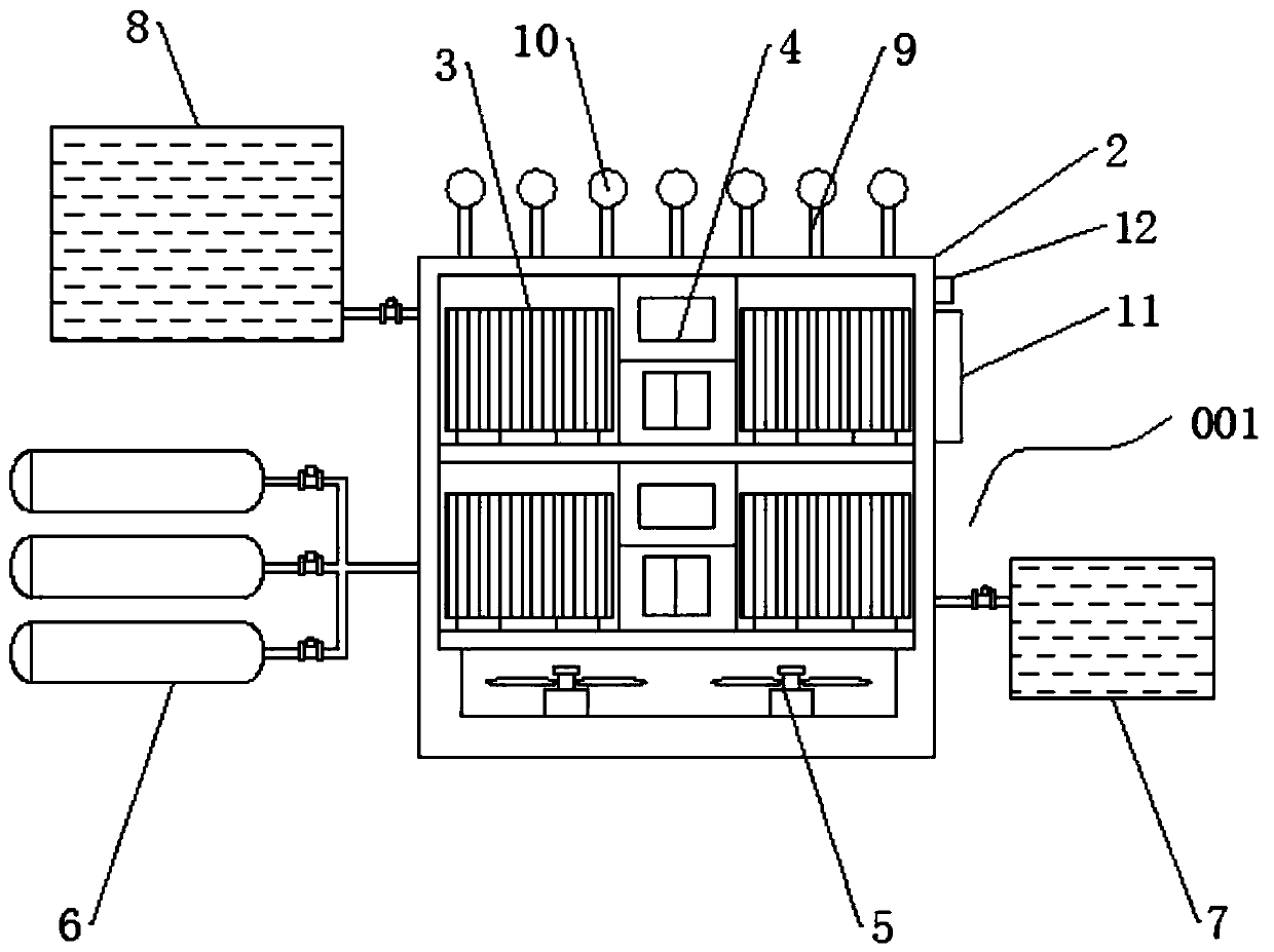
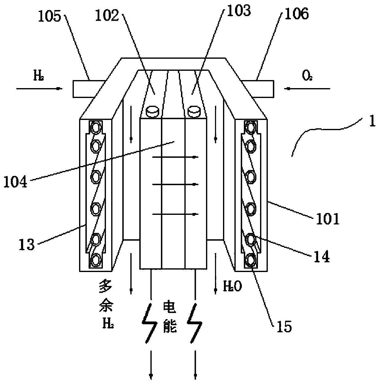
[0042] see figure 1 , a fuel cell vehicle hydrogen fuel cell stack and cooling device, including a fuel cell body 001, a high-pressure hydrogen tank 6 and an air compressor, the fuel cell body 001 includes a mounting shell 2 and a plurality of battery packs 3, and the mounting shell 2 is fixedly connected There is a pair of partitions, and a pair of partitions divide the installation shell 2 into two battery pack placement cavities and a wind cooling cavity, and the wind cooling cavity is located at the lower end of the installation shell 2, and the installation shell 2 is connected with a wide surface cooling The mechanism is used to dissipate the heat of the installation shell 2 as a whole. The wide-area heat dissipation mechanism includes a speed-regulating fan 5 and a fast heat dissipation column 9. A pair of speed-regulating fans 5 are installed in the wind cooling chamber, and a plurality of fast heat dissipation columns 9 are evenly distributed on the installation shell ...


PUM


Abstract

The invention discloses a hydrogen fuel battery pack of a fuel battery vehicle and a heat dissipation device, and belongs to the technical field of fuel cells. The hydrogen fuel battery pack of the fuel battery vehicle comprises a fuel cell body, a high-pressure hydrogen tank and an air compressor, and is characterized in that the fuel cell body comprises a mounting shell and a plurality of battery packs, a pair of partition plates is fixedly connected in the mounting shell, and the mounting shell is divided into two battery pack placement cavities and a wind power heat dissipation cavity by the pair of partition plates; a wind power heat dissipation cavity is positioned at the lower end part of the mounting shell, and a wide-area heat dissipation mechanism is connected to the mounting shell and comprises the speed regulation fans and the rapid heat dissipation columns; the pair of speed regulation fans are installed in the wind power heat dissipation cavity, and the plurality of rapidheat dissipation columns are evenly distributed at the upper end of the mounting shell, so that the uniformity of a temperature field of the battery pack in the using process can be guaranteed, the reliability and consistency of the battery performance are improved, and then the performance and operation safety of the whole vehicle are remarkably improved.

Description

technical field [0001] The invention relates to the technical field of fuel cells, and more specifically, relates to a hydrogen fuel cell stack and a cooling device for a fuel cell vehicle. Background technique [0002] The widespread use of new energy by humans has led to the rapid expansion of the secondary battery market. The current new energy system requires secondary batteries everywhere. Whether it is electric vehicles, wind energy, solar grid connection or grid peak regulation, there is an urgent need A cheap, reliable, safe and long-life secondary battery. The secondary batteries currently developed are mainly concentrated in lithium-ion batteries, high-temperature sodium-sulfur batteries, sodium-nickel-chloride batteries and vanadium flow batteries. These batteries have their own Advantages, such as lithium-ion batteries and high-temperature sodium-sulfur batteries have long life and high energy density, and vanadium redox flow batteries have theoretically unlimite...

Claims


Application Information

Patent Timeline
Patent Type & Authority Applications(China)
IPC IPC(8): H01M8/0271H01M8/04007H01M8/04014H01M8/04029H01M8/04089H01M8/04291H01M8/0432H01M8/04694H01M8/04746H01M8/1016
CPCH01M8/0271H01M8/04014H01M8/04029H01M8/04067H01M8/04097H01M8/04291H01M8/04365H01M8/04694H01M8/04768H01M8/1016H01M2250/20Y02E60/50
Inventor 李得波
Owner 李得波
Learn More