Miniaturized fluorescent optical fiber temperature measurement system

A technology of fluorescent optical fiber and temperature measurement module, which is applied to thermometers, thermometers, measuring devices and other directions with physical/chemical changes, which can solve the problems of cumbersome installation and fixing methods of circuit boards and mounts, large volume, and cumbersome installation methods of optical devices, etc. problems, to achieve the effect of reducing manpower, simple installation, and miniaturization

Inactive Publication Date: 2020-06-26
西安和其光电科技股份有限公司
View PDF7 Cites 1 Cited by
  • Summary
  • Abstract
  • Description
  • Claims
  • Application Information

AI Technical Summary

Problems solved by technology

[0007] In order to solve the technical problems of the existing photoelectric demodulation module, such as cumbersome installation of optical devices, cumbersome installation and fixing of circuit boards and mounting seats, and large volume, the present invention provides a miniaturized fluorescent optical fiber temperature measurement system

Method used


Image

  • Miniaturized fluorescent optical fiber temperature measurement system
  • Miniaturized fluorescent optical fiber temperature measurement system
  • Miniaturized fluorescent optical fiber temperature measurement system

Examples


Embodiment Construction

[0058] The content of the present invention will be further described in detail below in conjunction with the accompanying drawings and specific embodiments.

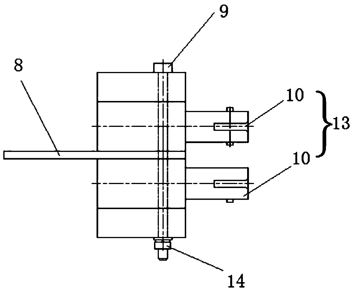
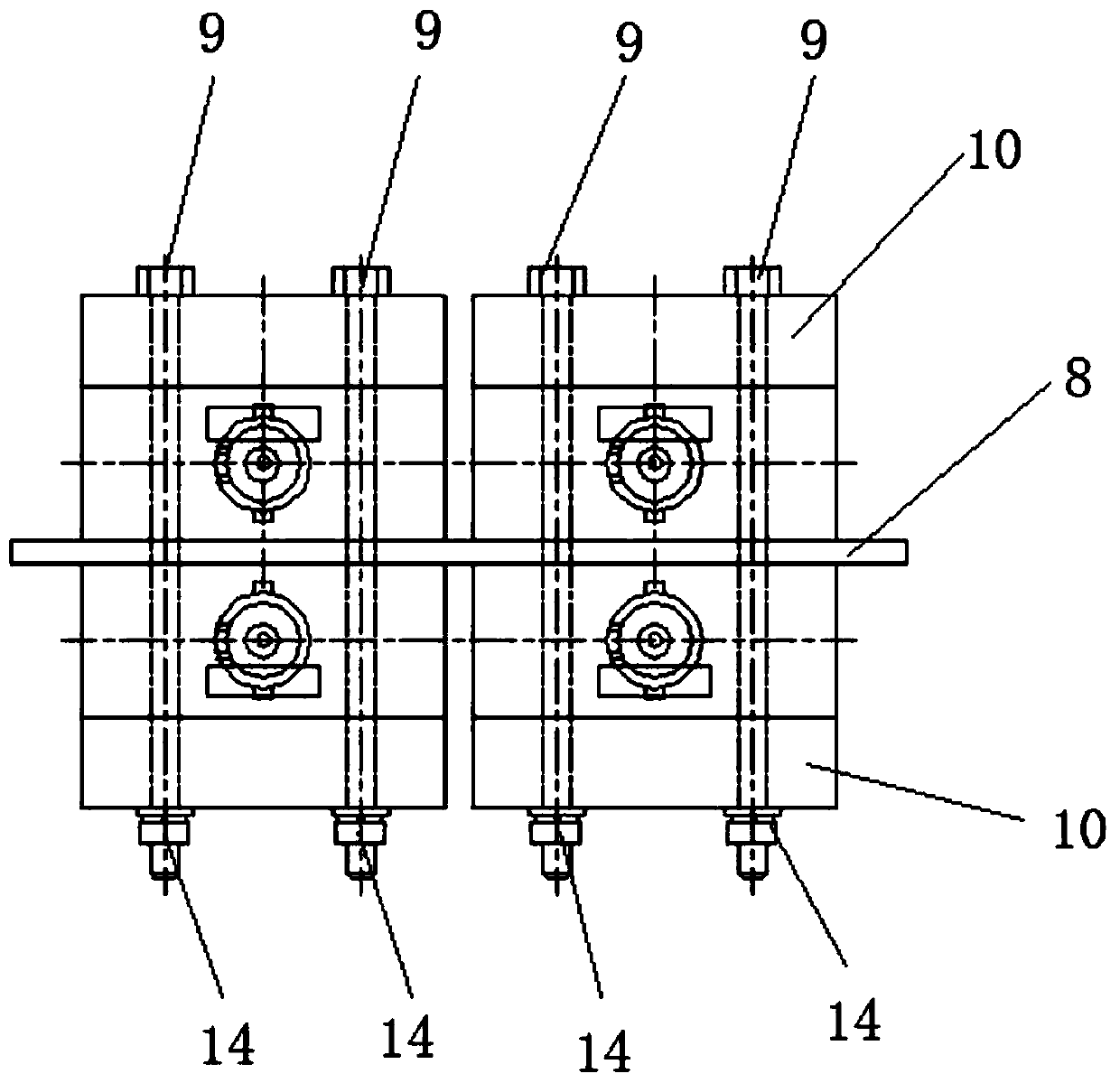
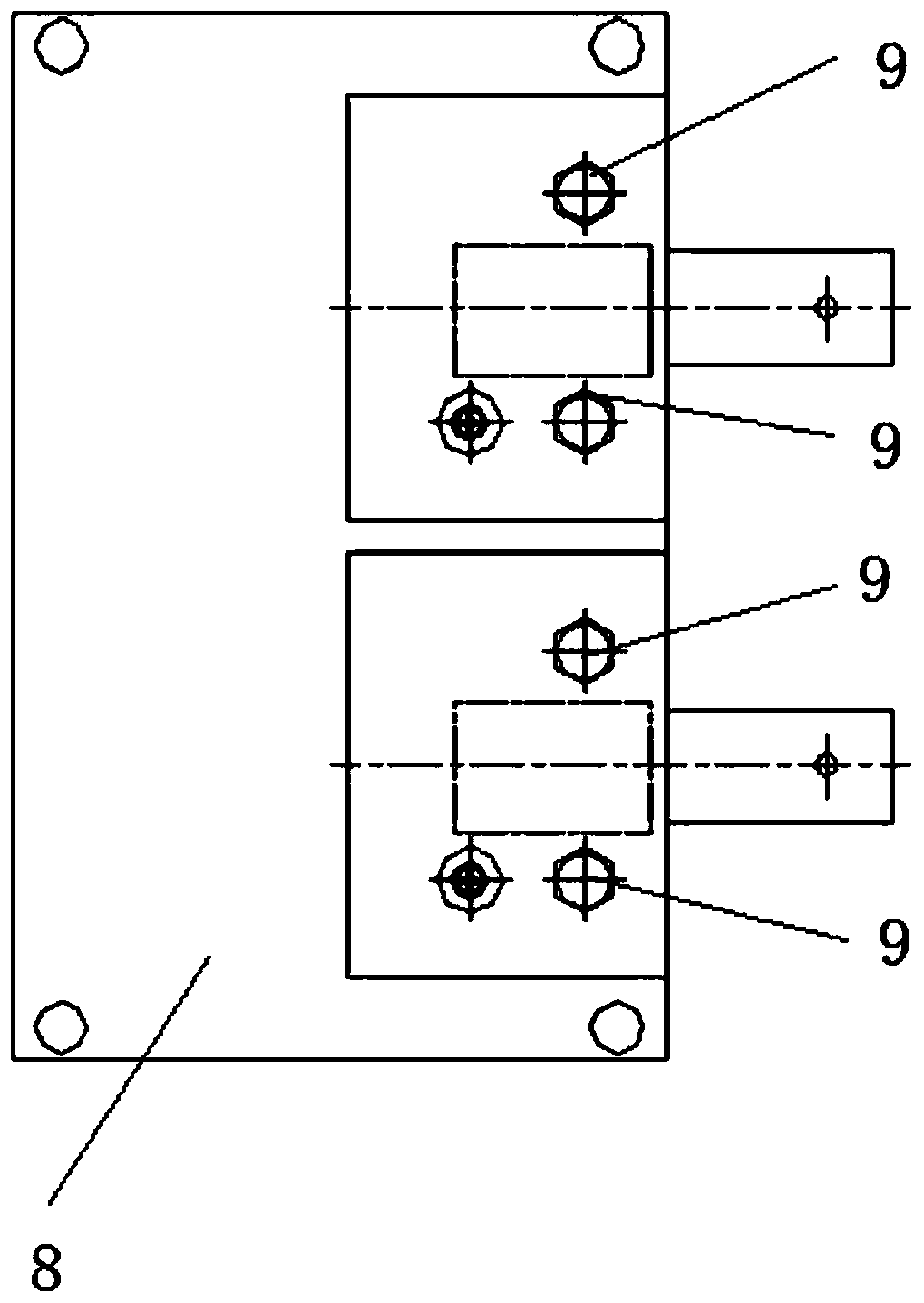
[0059] Such as Figure 1 to Figure 3 As shown, a miniaturized fluorescent optical fiber temperature measurement system includes a PCB board and at least one temperature measurement module unit 13 arranged on the PCB board 8; each temperature measurement module unit 13 includes 2 temperature measurement modules 10, 2 The temperature measuring modules 10 are symmetrically arranged on two substrate surfaces of the PCB board 8 .

[0060] Such as Figure 4 with Figure 5 As shown, the temperature measurement module 10 includes a mounting base 1, a circuit board 2, a light emitting diode 3, a photodetector 4, an optical fiber connector 5, a ball lens 6, and an optical filter 7; the mounting base 1 includes an upper mounting base body 12 and a lower mounting base body. The seat body 11; the upper mounting seat body 12 and t...


PUM

PropertyMeasurementUnit
Bending angleaaaaaaaaaa

Abstract

The invention provides a miniaturized fluorescent optical fiber temperature measurement system, and solves the problems that an existing photoelectric demodulation module is relatively tedious in optical device installation mode and relatively large in size. The temperature measurement system comprises a PCB and at least one temperature measurement module unit arranged on the PCB. Each temperaturemeasurement module unit comprises two temperature measurement modules which are symmetrically arranged on two substrate surfaces of the PCB respectively; each temperature measurement module comprisesa mounting base, a photoelectric detector, and a circuit board, a light emitting diode, an optical fiber connector, a ball lens and an optical filter which are positioned in the mounting base; the optical fiber connector is arranged outside the front part of the mounting base; the circuit board is used for exciting the light-emitting diode to emit light beams, the light beams are incident to theoptical filter, filtered and reflected by the optical filter, incident to the spherical lens, condensed by the spherical lens and transmitted to the external optical fiber; the photoelectric detectoris used for receiving the light beam transmitted by the external optical fiber and transmitted by the spherical lens and the optical filter; and the two temperature measurement modules of each temperature measurement module unit are fixed on the PCB through bolts.

Description

technical field [0001] The invention belongs to the field of fluorescent optical fiber measurement, in particular to a miniaturized fluorescent optical fiber temperature measurement system. Background technique [0002] At present, the fluorescent optical fiber temperature control system consists of a temperature demodulation module, an optical fiber interface, and a temperature measurement optical fiber containing fluorescent substances. The temperature measurement optical fiber is connected to the temperature demodulation module through the optical fiber interface, and the temperature demodulation module is embedded in the shell of the temperature demodulator. , only the optical fiber interface is exposed. One end of the temperature measuring optical fiber is connected to the temperature demodulator, and the other end contains a fluorescent substance embedded in the measured temperature point. The excitation light source in the temperature demodulator excites the fluoresc...

Claims


Application Information

Patent Timeline
IPC IPC(8): G01K11/32G01K1/14G01K1/08
CPCG01K11/32G01K1/14G01K1/08
Inventor 张文松张继超
Owner 西安和其光电科技股份有限公司
Why Eureka
Try Eureka