Exhaust system of silicon carbide smelting workshop

An exhaust system and silicon carbide technology, which is applied in the field of exhaust systems, can solve problems such as increasing the cost of silicon carbide smelting, environmental hazards in smelting workshops, and the inability to flexibly handle exhaust, so as to achieve improved exhaust effects, long service life, and energy saving Energy and Cost Effects

Pending Publication Date: 2020-06-26
平罗县荣昌碳化硅有限公司
View PDF0 Cites 0 Cited by
  • Summary
  • Abstract
  • Description
  • Claims
  • Application Information

AI Technical Summary

Problems solved by technology

[0002] The smelting of silicon carbide belongs to the field of large-scale chemical industry. The scale of the smelting furnace is very large, so the size of the smelting workshop is also large. At the same time, during the smelting process of silicon carbide, a variety of harmful gases will be produced, such as those produced by the basic reaction of smelting Carbon monoxide, sulfur dioxide, hydrogen sulfide, methyl mercaptan, etc. produced by wood chips and coke have caused great harm to the environment of the smelting workshop
Due to the unreasonable layout of the existing exhaust system in the smelting workshop and the excessively traditional selection of exhaust pipes and structures, it has caused problems such as poor exhaust effect and low exhaust efficiency. At the same time, there are also problems that cannot be handled flexibly Exhaust from different smelting areas results in a large degree of energy waste, which virtually increases the cost of smelting silicon carbide, which is not conducive to the long-term development of the enterprise

Method used


Image

  • Exhaust system of silicon carbide smelting workshop
  • Exhaust system of silicon carbide smelting workshop
  • Exhaust system of silicon carbide smelting workshop

Examples


Embodiment Construction

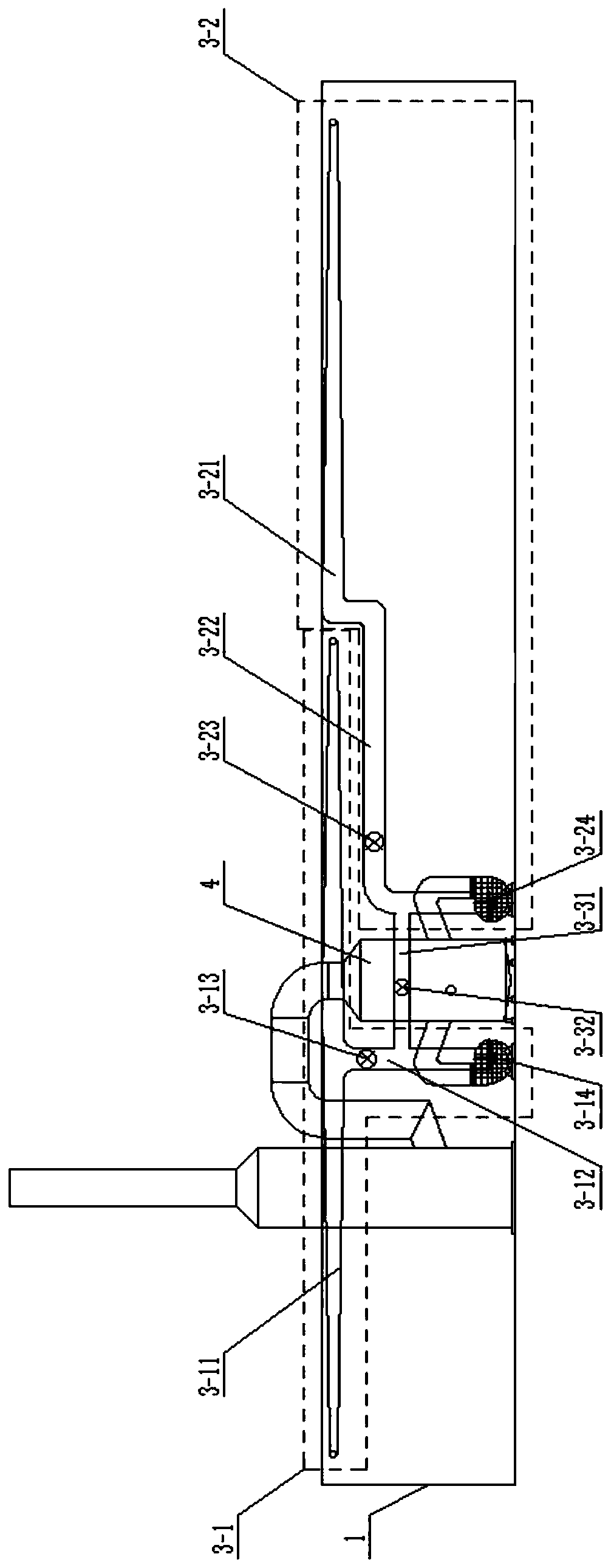
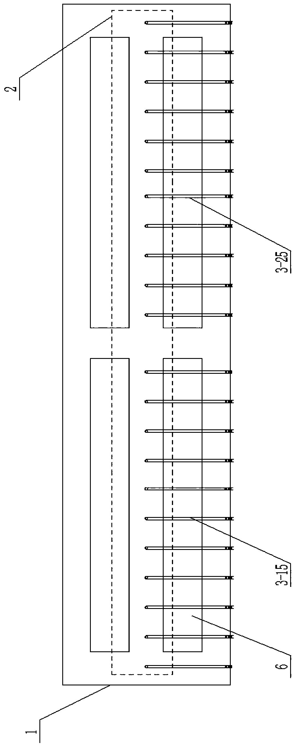
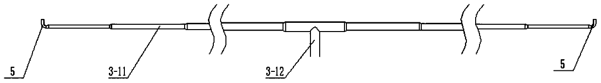
[0017] Such as Figure 1 to Figure 4 As shown, an exhaust system of a silicon carbide smelting workshop includes a smelting workshop 1, a smelting furnace 6 arranged in the smelting workshop 1; a gas collection building 2, a first exhaust mechanism 3-1, a second exhaust Mechanism 3-2, third connecting pipe 3-31, third valve 3-32, dust removal tower 4 and elbow pipe 5; the first exhaust mechanism 3-1 includes the first main air blower arranged outside the side wall of the smelting workshop 1 Pipe 3-11, first connecting pipe 3-12, first valve 3-13, first induced draft fan 3-14, and first branch air pipe 3-15 arranged outside the top wall of smelting workshop 1; the second row The gas mechanism 3-2 includes the second main air duct 3-21, the second connecting pipe 3-22, the second valve 3-23, the second induced draft fan 3-24 arranged outside the side wall of the smelting workshop 1, and the The second branch air duct 3-25 outside the top wall of the smelting workshop 1.

[001...


PUM


Abstract

The invention belongs to the technical field of silicon carbide processing, and relates to an exhaust system of a silicon carbide smelting workshop. The exhaust system includes a gas gathering building, a first exhaust mechanism and a dust removal tower. The first exhaust mechanism includes a first main air pipe, a first connecting pipe, a first valve, a first induced draft fan and a first branchair pipe. The diameter of the first main air pipe decreases gradually from the middle to the two ends, and the two ends are of closed structures. One end of the first connecting pipe communicates withthe largest pipe diameter of the first main air pipe, the first valve is arranged on a pipeline, the other end of the first connecting pipe is connected with the first induced draft fan and the dustremoval tower in sequence, one end of the first branch air pipe communicates with a pipeline of the first main air pipe, and the other end of the first branch air pipe extends into the gas gathering building. According to the exhaust system, by arranging the main air pipe with gradually varied pipe diameter, the exhaust effect and exhaust efficiency of the smelting workshop can be effectively improved; moreover, according to the smelting demand, an exhaust area can be flexibly used, the energy and cost are saved; and the layout of the system is more reasonable, and the processing cost is effectively saved.

Description

technical field [0001] The invention belongs to the technical field of silicon carbide processing and relates to an exhaust system for a silicon carbide smelting workshop. Background technique [0002] The smelting of silicon carbide belongs to the field of large-scale chemical industry. The scale of the smelting furnace is very large, so the size of the smelting workshop is also large. At the same time, during the smelting process of silicon carbide, a variety of harmful gases will be produced, such as those produced by the basic reaction of smelting Carbon monoxide, sulfur dioxide, hydrogen sulfide, methyl mercaptan, etc. produced by sawdust and coke have caused great harm to the environment of the smelting workshop. Due to the unreasonable layout of the existing exhaust system in the smelting workshop and the excessively traditional selection of exhaust pipes and structures, it has caused problems such as poor exhaust effect and low exhaust efficiency. At the same time, t...

Claims


Application Information

Patent Timeline
IPC IPC(8): F24F7/08F24F13/02F27D17/00
CPCF24F7/08F24F13/02F27D17/00
Inventor 王业周金荣赵永军周锐
Owner 平罗县荣昌碳化硅有限公司
Why Eureka
Try Eureka