SIW duplexer with three-dimensional stacked structure

A technology of three-dimensional stacking and duplexer, which is applied in the direction of waveguide devices, electrical components, circuits, etc., can solve the problems that cannot meet the application requirements of the millimeter-wave band active phased array antenna with small array element spacing, occupying an area, and not meeting the requirements of watts. Chip active phased array antenna signal vertical transmission requirements and other issues, to achieve the effect of easy high-density integration, easy miniaturization, easy high-density integration

Active Publication Date: 2020-06-23
10TH RES INST OF CETC
View PDF8 Cites 0 Cited by
  • Summary
  • Abstract
  • Description
  • Claims
  • Application Information

AI Technical Summary

Problems solved by technology

In the millimeter wave frequency band, the planar arrangement of multiple resonant cavities will also occupy too much area in the XY direction, which is limited by the 1 / 2 wavelength of the array element spacing, so it cannot meet the requirements of the millimeter wave band active phased array antenna. Application requirements for small array element spacing
In addition, the input and output SIW duplexers in the same plane do not meet the signal vertical transmission requirements of the tile-type active phased array antenna.
Therefore, the SIW reported in a large number of literatures has great limitations in the engineering application of microwave and millimeter wave systems such as active phased array antennas, and needs to be improved on this basis to meet practical applications

Method used


Image

  • SIW duplexer with three-dimensional stacked structure
  • SIW duplexer with three-dimensional stacked structure
  • SIW duplexer with three-dimensional stacked structure

Examples


Embodiment Construction

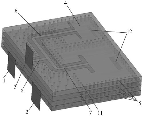
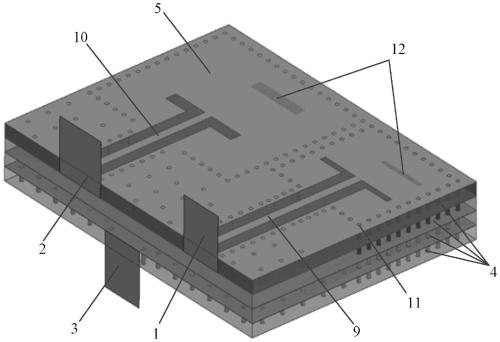
[0015] Refer to figure 1 , figure 2 . In the preferred embodiment described below, a three-dimensional stacked structure SIW duplexer includes: a transmitting stacked SIW filter 4 on a multilayer dielectric substrate, a receiving stacked SIW filter 5, a transmission output signal plane transmission line 6, The receiving input signal flat transmission line 7, the receiving and sending combined signal flat transmission line 8, the transmitting input signal flat transmission line 9, and the receiving output signal flat transmission line 10 are characterized in that: the transmitting laminated SIW filter 4 and the receiving laminated SIW filter 5 are all composed of The SIW resonant cavity composed of rectangularly arranged metallized through holes 11 arranged in each dielectric layer is vertically stacked; the transmitting output signal plane transmission line 6 and the receiving input signal plane transmission line 7 are located on the top metal surface of the SIW duplexer, and t...


PUM

PropertyMeasurementUnit
Lengthaaaaaaaaaa

Abstract

The invention discloses an SIW duplexer with a three-dimensional stacked structure, and relates to the field of microwave passive devices. The invention aims to provide an SIW duplexer which is easy to miniaturize and high in density integration and can realize vertical transmission of received and transmitted signals. The method is realized through the following technical scheme: a technical modeof combining a laminated SIW filter and a planar transmission line is adopted, the two laminated SIW filters used for transmitting and receiving are formed by vertically stacking SIW resonant cavities arranged on dielectric layers, the transmitting and receiving input and output transmission lines are located on the top metal surface of the SIW duplexer, and the transmitting and receiving input and output transmission lines and the top transmitting and receiving combined signal plane transmission line form a T-shaped structure after being bent. The input ports and the output ports are positioned on different planes of the top layer and the bottom layer; and the multiple sections of planar transmission lines located at the top layer and the bottom layer respectively perform T-shaped combination and horizontal lead-out on the input and output ports of the transceiving filter to form the three-dimensional stacked structure SIW duplexer meeting the actual application requirements of the tile type active phased array antenna under the millimeter wave frequency band.

Description

Technical field [0001] The invention relates to the field of microwave passive devices, a three-dimensional stacked structure SIW (Substrate Integrated Waveguide) SIW duplexer. Background technique [0002] SIW duplexer is the main accessory of different frequency duplex radio and repeater. Its function is to isolate the transmitting and receiving signals, ensuring that both receiving and transmitting can work normally at the same time. It is composed of two sets of bandpass filters with different frequencies. Substrate Integrated Waveguide (SIW) technology is one of the emerging and hotspot technologies in microwave passive direction in recent years. A substrate integrated waveguide filter is a filter implemented on a dielectric substrate. Its performance is similar to a rectangular waveguide filter, but it is a planar circuit. It has the characteristics of high quality factor, large power capacity, easy processing, and easy integration. The filter based on the substrate inte...

Claims


Application Information

Patent Timeline
IPC IPC(8): H01P1/20H01P1/208
CPCH01P1/20H01P1/208
Inventor 朱勇陆宇
Owner 10TH RES INST OF CETC
Why Eureka
Try Eureka