
Optical system for generating controllable convergent vortex light beams

A vortex beam, optical system technology, applied in the field of optical systems

Inactive Publication Date: 2020-06-23
UNIV OF ELECTRONICS SCI & TECH OF CHINA
View PDF5 Cites 3 Cited by
  • Summary
  • Abstract
  • Description
  • Claims
  • Application Information

AI Technical Summary

Problems solved by technology

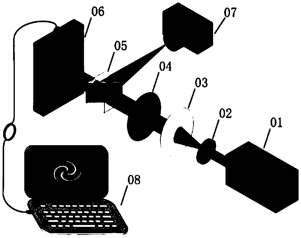
[0007] In order to solve the problem of how to use a relatively simple system and method to generate a controllable converging vortex beam, the present invention proposes an optical system that can generate a controllable converging vortex beam

Method used


Image

  • Optical system for generating controllable convergent vortex light beams
  • Optical system for generating controllable convergent vortex light beams
  • Optical system for generating controllable convergent vortex light beams

Examples


Embodiment Construction

[0025] specific implementation plan

[0026] The method for generating and controlling a converging vortex beam is characterized in that the method includes the following steps.

[0027] Step 1: Program the phase modulation grayscale image on the computer and import it into the spatial light modulator.

[0028] The phase modulation grayscale image consists of three parts.

[0029] One is the virtual lens part, its phase distribution is as follows figure 2 As shown in (a), its transmission function is expressed as:

[0030]

[0031] Wherein, x and y represent the Cartesian coordinates of the working surface of the spatial light modulator, the horizontal axis of the working surface is the x axis, and the vertical axis is the y axis. f represents the focal length of the virtual lens, and k represents the wave number.

[0032] The second is the vortex phase part, its phase distribution is as follows figure 2 As shown in (b), its transmission function is expressed as:

...


PUM


Abstract

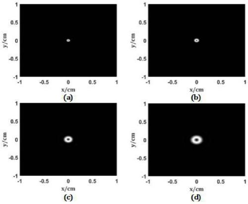
The invention relates to an optical system for generating controllable convergent vortex light beams. Main devices comprise a laser, a light beam shaping system, a spatial light modulator and a CCD camera. In the system, a spiral phase plate, a lens and a diaphragm are equivalently replaced by a phase gray scale modulation diagram, converged vortex light beams can be generated, and the focal length of the light beams and the radius of an annular light spot at a focal plane can be adjusted by modifying parameters of the phase gray scale diagram.

Description

technical field [0001] The invention relates to an optical system for generating controllable converging vortex beams, belonging to the technical field of vortex light. Background technique [0002] Vortex light is a beam with a helical wavefront. Compared with ordinary photons, vortex photons carry orbital angular momentum. Therefore, vortex light has important application value in optical communication, astronomical observation, microscopic imaging and particle manipulation. [0003] In many application scenarios such as particle manipulation, vortex light coupling to optical fiber, etc., it is necessary to converge the vortex beam. The traditional method is to first use the vortex phase plate to generate the vortex beam and then use the lens to converge. This design will produce some disadvantages. [0004] First of all, if the physical spiral phase plate is not replaced, the topological charge of the generated vortex light cannot be changed. The phase change period of t...

Claims


Application Information

Patent Timeline
IPC IPC(8): G02B27/09
CPCG02B27/0938G02B27/0955
Inventor 江萍牛野杨华军
Owner UNIV OF ELECTRONICS SCI & TECH OF CHINA
Learn More