
Manufacturing method of LTCC substrate double-face cavity structure

A manufacturing method and a cavity technology, which are applied in semiconductor/solid-state device manufacturing, electric solid-state devices, semiconductor devices, etc., can solve problems such as decreased alignment accuracy between sub-module layers, local bending of substrates, and unfavorable substrate flatness, etc., to achieve The effect of good double-sided cavity quality, alignment accuracy between high layers, and good process stability

Active Publication Date: 2020-06-19
SOUTHWEST CHINA RES INST OF ELECTRONICS EQUIP
View PDF4 Cites 6 Cited by
  • Summary
  • Abstract
  • Description
  • Claims
  • Application Information

AI Technical Summary

Problems solved by technology

In the patent "Multilayer Ceramic Double-sided Complex Cavity Structure Forming Method", the overall structure of the silicone rubber punch is used as the bottom filling structure, the semi-fluid soft silicone is used as the upper filling, and then the whole is placed on the rigid laminated backplane for lamination. , to make a double-sided cavity LTCC substrate. The silicone rubber punch of this method can be reused, and the lamination operation is simple, but it is necessary to make a silicone rubber punch for each product, and the processing accuracy of the punch and the repeated use At the same time, during the process of stacking each layer of green ceramic sheets on the silicone rubber punch through positioning pins, the adaptive adjustment of the hollow cavity of the green ceramic sheet to the position of the silicone rubber punch may easily lead to partial The alignment accuracy between the layers is reduced. Moreover, when laminating in this method, the back of the entire LTCC substrate body is placed on the flexible silicone layer, which lacks rigid planar support for the substrate body. When the cavity structure is complex, It is prone to local bending of the substrate, which is not conducive to the improvement of the flatness of the final substrate
In the patent "a method for forming double-sided cavities of multilayer ceramic substrates", the substrate with double-sided cavities is divided into sub-modules, and each sub-module is transformed into a single-sided cavity structure, and the sub-modules of the single-sided cavity are respectively processed Pre-lamination, and then each sub-module is stacked again for final lamination. This method can achieve better flatness of the double-sided cavity bottom, but the process is complicated, and the deformation of each sub-module after pre-lamination will cause the sub-module Alignment accuracy drops between layers
The patent "Manufacturing method of LTCC substrate with double-sided cavity structure" uses inserts to manufacture double-sided cavities, and uses carbon-based sacrificial materials as inserts for the back cavity, which can achieve good cavity quality, but needs to be specific to each The product produces high-precision silicone inserts and carbon-based material inserts, and each insert needs to be placed in the cavity of the substrate during lamination. The operation is more complicated, especially when the depth of the cavity is shallow. It is easy to slip and misplace during packaging, and there is a quality risk
The patent "a packaging shell with a double-sided cavity" discloses a ceramic packaging shell with a double-sided cavity structure, but does not involve the molding method of the double-sided structure ceramic substrate

Method used


Image

  • Manufacturing method of LTCC substrate double-face cavity structure
  • Manufacturing method of LTCC substrate double-face cavity structure

Examples


Embodiment 1

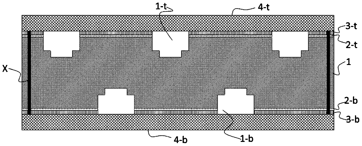
[0030] The invention provides a method for manufacturing a double-sided cavity structure of an LTCC substrate, and the specific steps are as follows:

[0031] Step 1: If figure 1 As shown, the top rigid support piece 3t and the bottom rigid support piece 3b are made according to the cavity structure, the material is stainless steel, the thickness is 0.4mm, and the processing method is laser cutting.

[0032] Step 2: If figure 1 As shown, the top release film 2t and the bottom release film 2b are made according to the structure of the cavity. The material is PET film coated with silicone oil, the thickness is 0.1mm, and the processing method is laser cutting.

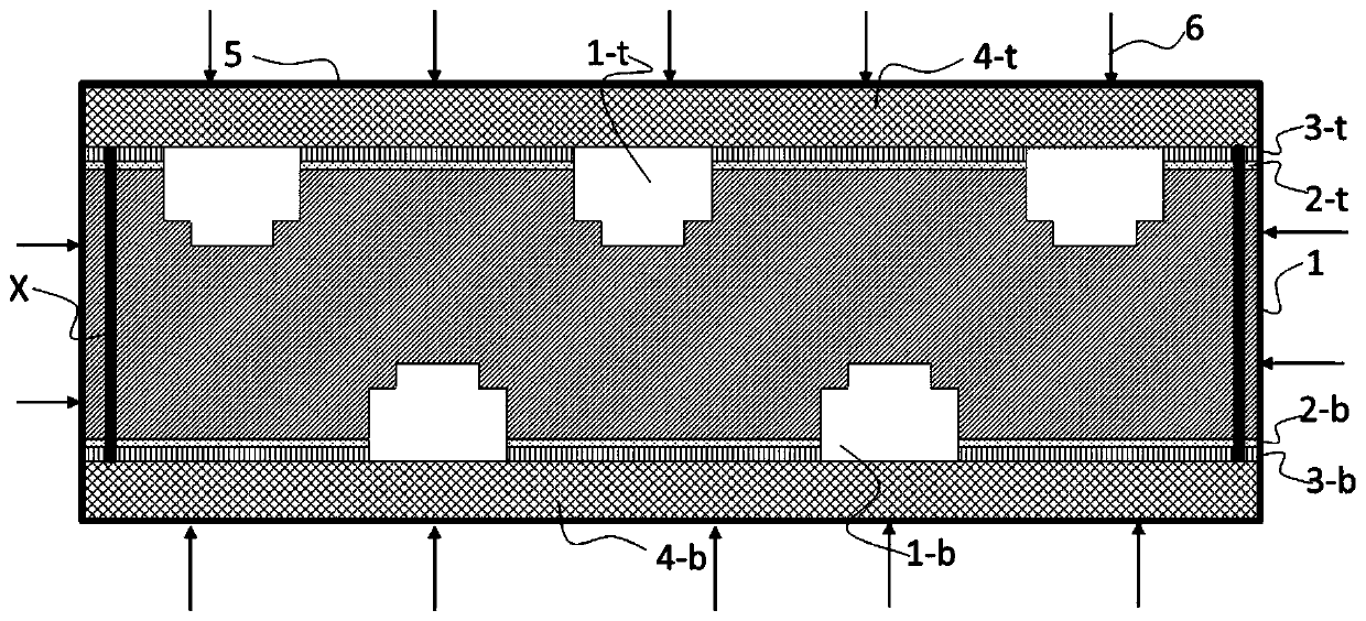
[0033] Step 3: If figure 1 As shown, the Ferro-A6M material system is selected, the through holes are made on the LTCC green ceramic sheet by the drilling and hole filling process, the conductor pattern is made by the screen printing process, and the cavity is made by laser processing or mechanical punching. After the...


PUM

PropertyMeasurementUnit
thicknessaaaaaaaaaa
thicknessaaaaaaaaaa
thicknessaaaaaaaaaa

Abstract

The invention relates to the field of LTCC circuit substrate processing, and discloses a manufacturing method of a LTCC substrate double-face cavity structure. Rigid supporting pieces at the top and the bottom are used for providing rigid supporting during product lamination, and pressure transmission to the interiors of cavities in the front face and the back face in the lamination process is achieved by opening cavities in the rigid supporting pieces. Meanwhile, the planar soft silica gel sheets are used for replacing filling protection objects such as filling embedded blocks and silicone rubber male dies on the front face and the back face, all that is needed is to spread the whole face, operation is extremely easy, alignment and embedding problems do not need to be considered, the filling difficulty of the filling protection objects is greatly reduced, and good process stability is achieved. According to the forming method, a traditional LTCC lamination technology is not changed, high interlayer alignment precision of the product can be obtained while good double-face cavity quality and high flatness of the substrate are guaranteed, and manufacturing of the high-performance LTCC substrate is achieved.

Description

Technical field [0001] The invention relates to the field of LTCC circuit substrate processing, and in particular to a method for manufacturing a double-sided cavity structure of an LTCC substrate. Background technique [0002] LTCC technology has been widely used in aviation, aerospace, missile launch, communications and other fields due to its excellent high-frequency performance, high integration density and high reliability. As the demand for miniaturization and lightweighting of information equipment systems continues to increase, more chips need to be integrated on a single LTCC substrate to achieve more functions. At the same time, due to the requirements for coplanar / common ground, impedance matching, electromagnetic shielding, etc. for high-frequency signal transmission, a complex-structured cavity must be opened on the LTCC substrate to achieve reasonable assembly of functional chips. [0003] Based on the integration requirements of high density, multi-function, ...

Claims


Application Information

Patent Timeline
Patent Type & Authority Applications(China)
IPC IPC(8): H01L21/48H01L23/15
CPCH01L21/4807H01L23/15
Inventor 王娜岳帅旗杨宇黄翠英张刚徐洋
Owner SOUTHWEST CHINA RES INST OF ELECTRONICS EQUIP
Learn More