A magnetic-optical diaphragm, a magneto-optical sensor, a welding seam detection device and method
A technology for welding seam detection and magneto-rotation, which is used in measuring devices, instruments, scientific instruments, etc., can solve the problems of low quality of magneto-optical images and small illumination area of light source, and achieves improved image quality, resolution and weld seam. Defect detection accuracy, the effect of increasing the rotation angle
- Summary
- Abstract
- Description
- Claims
- Application Information
AI Technical Summary
Problems solved by technology
Method used
Image
Examples
Embodiment 1
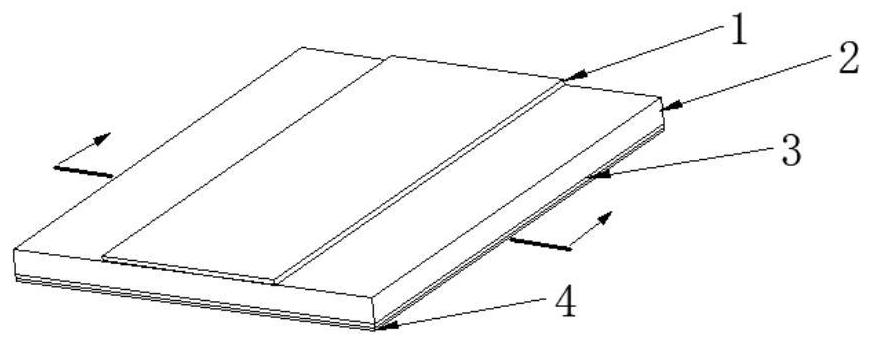
[0042] This embodiment provides a magneto-optical diaphragm to solve the problem of small Faraday rotation angle caused by the small thickness of the magneto-optical diaphragm.
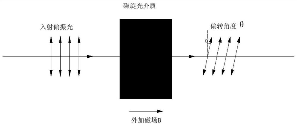
[0043] The principle of magneto-optical imaging is based on the Faraday magneto-optical rotation effect, such as figure 1As shown, the polarization direction of polarized light will rotate at a certain angle when passing through the optically active medium with an external magnetic field. This rotation angle is called the Faraday rotation angle θ. The magnetic induction intensity component B in the propagation direction of the light is proportional, that is:
[0044] θ=V×B×d
[0045] In the formula: V is a coefficient that characterizes the magneto-optical properties, which depends on the material properties of the magneto-optical medium and the working wavelength of the light, and is called the Verdet constant.
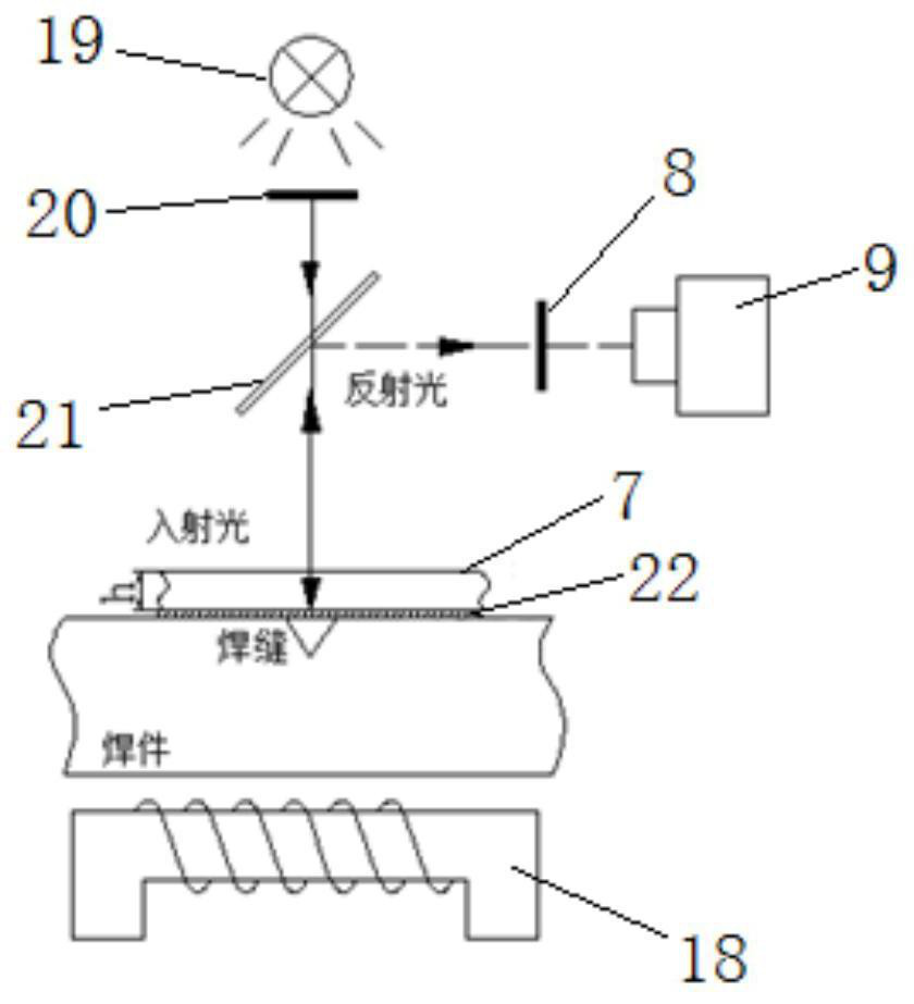
[0046] Such as figure 2 As shown, in the existing magneto-optical imaging detection ...
Embodiment 2
[0058] This embodiment provides a magneto-optical sensor, such as Figure 5 As shown, it includes housing 5, line laser emitter 6, analyzer 8, CCD camera 9 and the magnetic optical rotation diaphragm 7 described in Embodiment 1. Since the light emitted by line laser emitter 6 is polarized light, there is no need Polarizers convert light into polarized light. The casing 5 is a closed structure, and its interior is a cavity for installing a line laser emitter 6 , a polarizer 8 , a CCD camera 9 , and a magnetic-optical diaphragm 7 . In this embodiment, the housing 5 has a rectangular parallelepiped structure. It can be understood that in other embodiments, the housing 5 can also be in other shapes, such as spherical, as long as the above components can be installed and the installation position can be guaranteed.
[0059] In this embodiment, the magnetic optical rotation diaphragm 7 is fixed on the bottom surface of the housing 5, the line laser emitter 6 is located on one side ...
Embodiment 3
[0067] This embodiment provides a weld detection device, such as Figure 8 As shown, it includes a magnetic field generator 14, a linear motion device, a computer 17, a main control board 15 and the magneto-optical sensor 11 described in the second embodiment. To detect relative movement of the weld seam, a linear motion device is provided in this embodiment to move the weldment 12 relative to the magneto-optical sensor 11 .
[0068] The magneto-optical sensor 11 is arranged above the linear motion device, and the magneto-optic sensor 11 is connected to the computer 17 through wires. In this embodiment, the linear motion device includes a motion platform 13, a support, a lead screw and a motor 16, the lead screw passes through the support horizontally, and both ends of the lead screw are respectively connected to the support in rotation.
[0069] One end of the lead screw is connected to a motor 16 , which drives the lead screw to rotate; the motor 16 is connected to a comput...
PUM
| Property | Measurement | Unit |
|---|---|---|
| thickness | aaaaa | aaaaa |
| thickness | aaaaa | aaaaa |
Abstract
Description
Claims
Application Information
 - R&D
- Intellectual Property
- Life Sciences
- Materials
- Tech Scout
- Unparalleled Data Quality
- Higher Quality Content
- 60% Fewer Hallucinations
Browse by: Latest US Patents, China's latest patents, Technical Efficacy Thesaurus, Application Domain, Technology Topic, Popular Technical Reports.
© 2025 PatSnap. All rights reserved.Legal|Privacy policy|Modern Slavery Act Transparency Statement|Sitemap|About US| Contact US: help@patsnap.com


