
Qualitative diagnosis method for power frequency fault of rotary machinery

A technology of rotating machinery and diagnostic methods, applied in the testing of mechanical components, testing of machine/structural components, instruments, etc., can solve the problems of unfavorable differential information extraction and expression, accurate qualitative diagnosis of rotor power frequency faults, and neglect of diagnostic information and other issues to achieve the effect of promoting further improvement and development and realizing qualitative diagnosis

Active Publication Date: 2020-06-19
XI'AN UNIVERSITY OF ARCHITECTURE AND TECHNOLOGY
View PDF8 Cites 0 Cited by
  • Summary
  • Abstract
  • Description
  • Claims
  • Application Information

AI Technical Summary

Problems solved by technology

The above methods basically take the total power frequency component in the original vibration signal as the analysis object, which includes both the power frequency component of the pure fault response and the power frequency component of the initial state (no fault or normal state), and The mixing of the initial power frequency component will submerge or interfere with some key fault information carried by the pure fault response power frequency component, which is not conducive to the extraction and expression of differentiated information
In addition, most of the existing methods mainly focus on the feature extraction of the rotor precession trajectory at a single moment, ignoring the hidden diagnostic information of these features over time, and the methods suitable for extracting and characterizing the changes of these features are also very scarce.
These unfavorable factors have brought great troubles to the accurate qualitative diagnosis of rotor power frequency faults, and have seriously affected the troubleshooting efficiency of rotating machinery.

Method used


Image

  • Qualitative diagnosis method for power frequency fault of rotary machinery
  • Qualitative diagnosis method for power frequency fault of rotary machinery
  • Qualitative diagnosis method for power frequency fault of rotary machinery

Examples


Embodiment Construction

[0022] The present invention will be further elaborated below in conjunction with the accompanying drawings and embodiments.

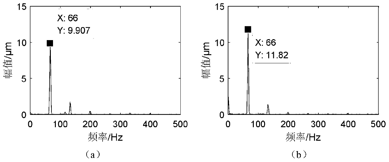
[0023] Embodiment The power frequency fault induced by the rotor unbalance problem is simulated on the Bentley rotor test bench, and its structure diagram is as follows figure 1 As shown: the test bench includes motor A and rotor B. The rotor of motor A is supported by 1# and 2# bearings, and the rotor B is supported by 3# and 4# bearings. The two rotors are connected by flexible coupling C. The 1# and 2# balance plates for adding test weights are symmetrically arranged in the span of the rotor B along the axial direction. 16 threaded holes are equiangularly and evenly distributed on the circumference of a balance plate with a radius of 32mm, which are used to add test weights in the rotor unbalance simulation experiment. Install two vibration sensors perpendicular to each other in the X and Y directions of the vibration measuring belts of the 3# and ...


PUM


Abstract

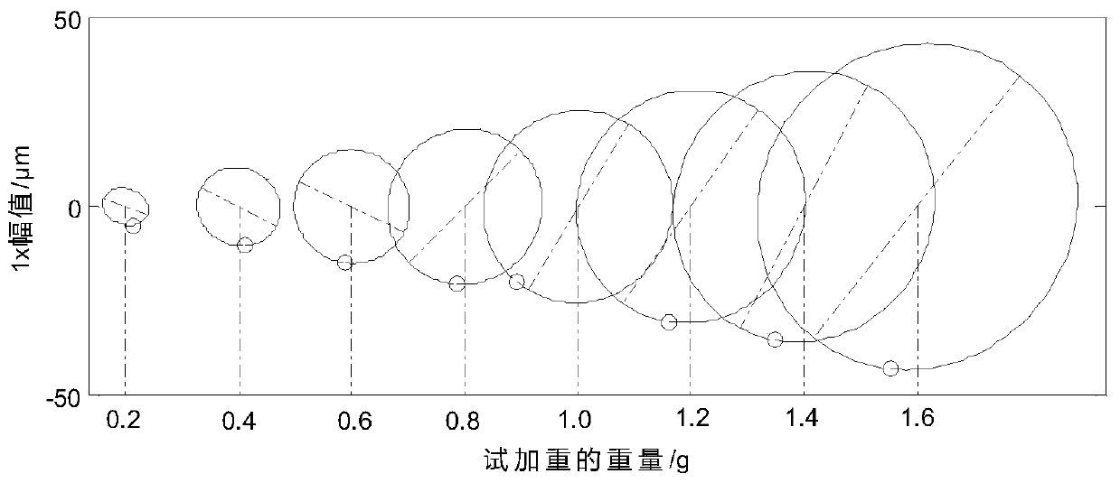
The invention discloses a qualitative diagnosis method for a power frequency fault of rotary machinery. The method comprises the following steps: firstly, synchronously acquiring multiple groups of shaft vibration displacement signals and corresponding key phase signals at two measuring points which are vertically arranged at a rotor fault response sensitive section; then extracting a pure fault power frequency component in the vibration signal by using a two-dimensional holographic difference spectrum, and finally constructing a two-dimensional holographic difference spectrum waterfall plot corresponding to the power frequency and a characteristic trend plot thereof to completely describe the change characteristics of pure fault procession trajectory characteristics. According to the method, the change rule of pure fault power frequency track characteristics can be visually reflected, differentiated information is effectively mined from the fault development process, and accurate qualitative diagnosis of the rotor power frequency fault is realized.

Description

technical field [0001] The invention belongs to the technical field of mechanical fault diagnosis, and in particular relates to a qualitative diagnosis method for power frequency faults of rotating machinery. Background technique [0002] Rotor power frequency fault is the most common type of vibration problem in rotating machinery. There are many factors that induce this type of fault. Because of these different types and natures of faults, the rotor vibration response is characterized by the power frequency component as the dominant fault component. The response signals of different faults are superimposed and coupled with each other, and it is often difficult for diagnostic engineers to accurately distinguish these faults. According to the analysis of the rotor vibration mechanism, the reasons for the power frequency failure of the rotor can be roughly summarized into two aspects. On the one hand, the rotor balance state deteriorates during the operation of the unit, whic...

Claims


Application Information

Patent Timeline
Patent Type & Authority Applications(China)
IPC IPC(8): G01M13/00G01M13/045
CPCG01M13/00G01M13/045
Inventor 瞿雷张小龙刘金颂曹辉
Owner XI'AN UNIVERSITY OF ARCHITECTURE AND TECHNOLOGY
Learn More