Flow regulating valve

A flow regulating valve and valve body technology, applied in valve details, valve device, valve operation/release device, etc., can solve problems such as inability to quickly and easily complete valve control work, poor valve stability, and valve damage. To achieve the effect of convenient and fast valve adjustment and control process, and improve stability

Active Publication Date: 2020-06-19
山东耐斯特炭黑有限公司
View PDF8 Cites 0 Cited by
  • Summary
  • Abstract
  • Description
  • Claims
  • Application Information

AI Technical Summary

Problems solved by technology

[0003] However, a kind of flow regulating valve currently on the market has the following problems during use. a. Since the existing flow control valve is partly installed in an outdoor environment, and in order to prevent pipeline pollution and corrosion, the erection of pipelines is suspended The way of erection makes the overall flow regulating valve also in a suspended state, resulting in poor stability of the entire valve. At the same time, when the valve is opened and closed manually, turning the handwheel will drive the connection between the valve and the pipeline to a certain extent. Offset occurs at the position, which is easy to cause damage to the valve; b. Based on the existing valves are opened and closed by handwheel rotation, the operator cannot complete the control work of the team valve conveniently and quickly under certain circumstances

Method used


Image

  • Flow regulating valve
  • Flow regulating valve
  • Flow regulating valve

Examples


Embodiment Construction

[0023] The embodiments of the present invention will be described in detail below with reference to the accompanying drawings, but the present invention can be implemented in many different ways defined and covered by the claims.

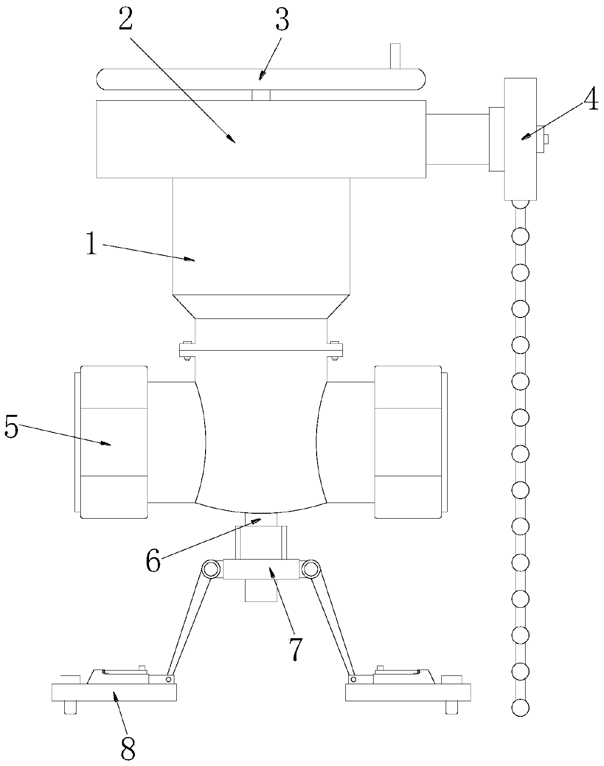
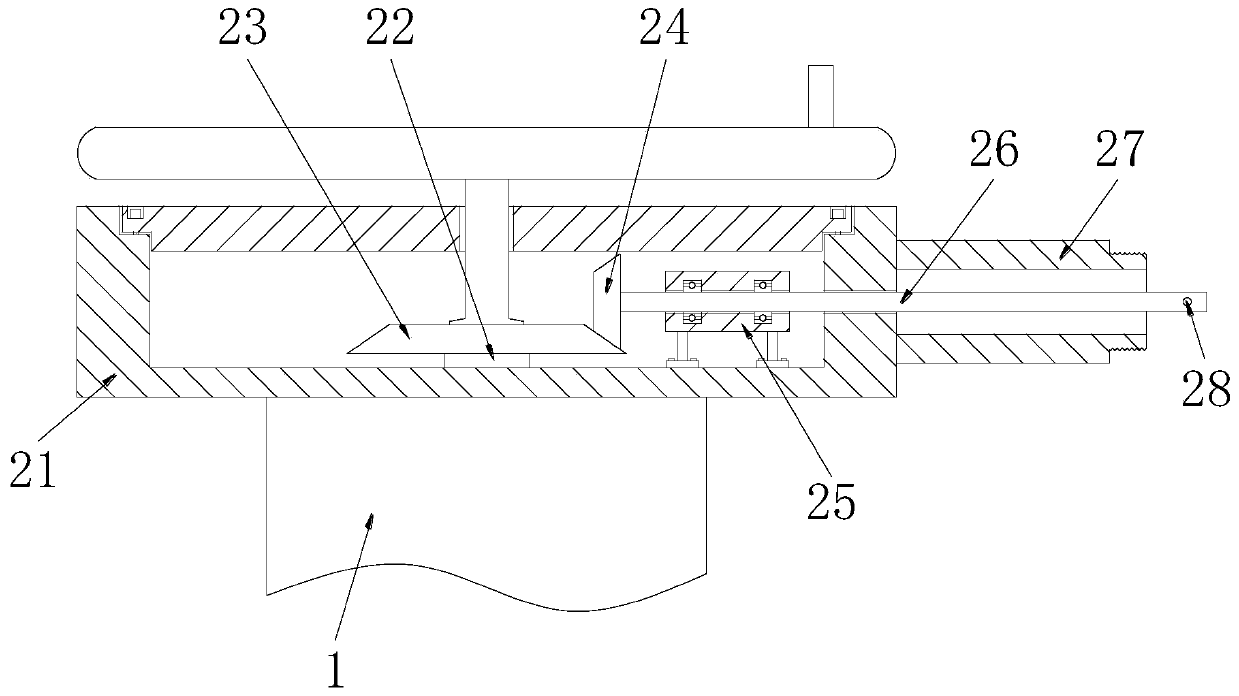
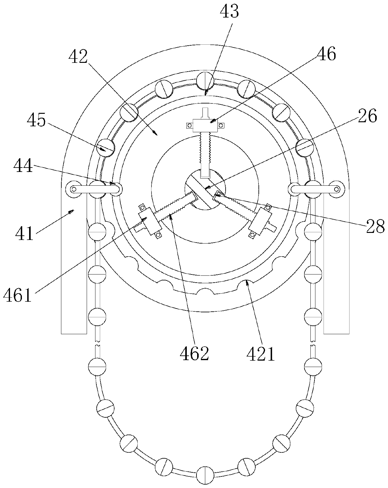
[0024] Such as Figure 1 to Figure 6 As shown, a flow regulating valve includes a valve body 1, a connecting mechanism 2, a rotating hand wheel 3, a driving mechanism 4, a connecting terminal 5, a threaded connecting rod 6, a supporting mechanism 7 and a fixing mechanism 8. The valve body 1 The top of the connecting mechanism 2 is provided with a connecting mechanism 2, the upper end of the connecting mechanism 2 is equipped with a rotating handwheel 3, one side of the connecting mechanism 2 is connected with a driving mechanism 4, and both ends of the bottom of the valve body 1 are provided with connecting terminals 5, the valve body 1 The central position of the outer wall of the bottom of the bottom is welded with a threaded connecting rod 6, and...


PUM


Abstract

The invention relates to a flow regulating valve which comprises a valve body, a connecting mechanism, a rotating handwheel, a drive mechanism, connecting end heads, a threaded connecting rod, a supporting mechanism and a fixing mechanism. The connecting mechanism is arranged on the top part of the valve body; the rotating handwheel is arranged at the upper end of the connecting mechanism; the drive mechanism is connected to one side of the connecting mechanism; the connecting end heads are arranged at two ends of the bottom part of the valve body; the threaded connecting rod is welded to thecenter of the outer wall of the bottom part of the valve body; the supporting mechanism is arranged on the outer wall of the threaded connecting rod in a screw-thread fit way; the fixing mechanism isconnected to the bottom part of the supporting mechanism; a connecting shell is welded to the outer wall of the top part of the valve body; a valve rod is arranged in the center in the connecting shell; the top end of the valve rod is connected with the rotating handwheel; a first bevel gear is welded to the outer wall of the valve rod; a second bevel gear meshes one side of the first bevel bear;and a rotary shaft is welded to one side of the second bevel gear. According to the flow regulating valve provided by the invention, the overalls stability of the valve is effectively improved, and meanwhile, the adjustment control process is convenient and fast.

Description

technical field [0001] The invention relates to the technical field of valves, in particular to a flow regulating valve. Background technique [0002] The valve is a pipeline accessory used to open and close the pipeline, control the flow direction, adjust and control the parameters of the conveying medium. It is a control component in the fluid conveying system, with the functions of cut-off, adjustment, flow diversion, reverse flow prevention, pressure stabilization, flow diversion or overflow pressure relief. Valves used in fluid control systems, from the simplest globe valves to various valves used in extremely complex automatic control systems. Valves can be used to control the flow of various types of fluids such as air, water, steam, various corrosive media, mud, oil, liquid metal and radioactive media. The flow control valve is one of many valves [0003] However, a kind of flow regulating valve currently on the market has the following problems during use. a. Sin...

Claims


Application Information

Patent Timeline
Patent Type & Authority Applications(China)
IPC IPC(8): F16K31/44F16K31/72F16K31/53F16K51/00
CPCF16K31/00F16K31/44F16K31/53F16K51/00
Inventor 储国亲
Owner 山东耐斯特炭黑有限公司
Why Eureka
Try Eureka