A low carbon monoxide miniature hydrogen generation device using methanol steam reforming

A technology of steam reforming and carbon monoxide, applied in hydrogen/synthesis gas production, hydrogen, inorganic chemistry, etc., can solve the problems of insufficient portability and poor hydrogen production effect, and achieve easy integration, compact structure, and high methanol conversion rate Effect

Active Publication Date: 2021-09-28
HARBIN INST OF TECH
View PDF6 Cites 0 Cited by
  • Summary
  • Abstract
  • Description
  • Claims
  • Application Information

AI Technical Summary

Problems solved by technology

[0006] In order to solve the problems of poor hydrogen production effect and insufficient portability of existing hydrogen production devices, the present invention further provides a low carbon monoxide miniature hydrogen generation device using methanol steam reforming

Method used


Image

  • A low carbon monoxide miniature hydrogen generation device using methanol steam reforming
  • A low carbon monoxide miniature hydrogen generation device using methanol steam reforming
  • A low carbon monoxide miniature hydrogen generation device using methanol steam reforming

Examples


specific Embodiment approach 1

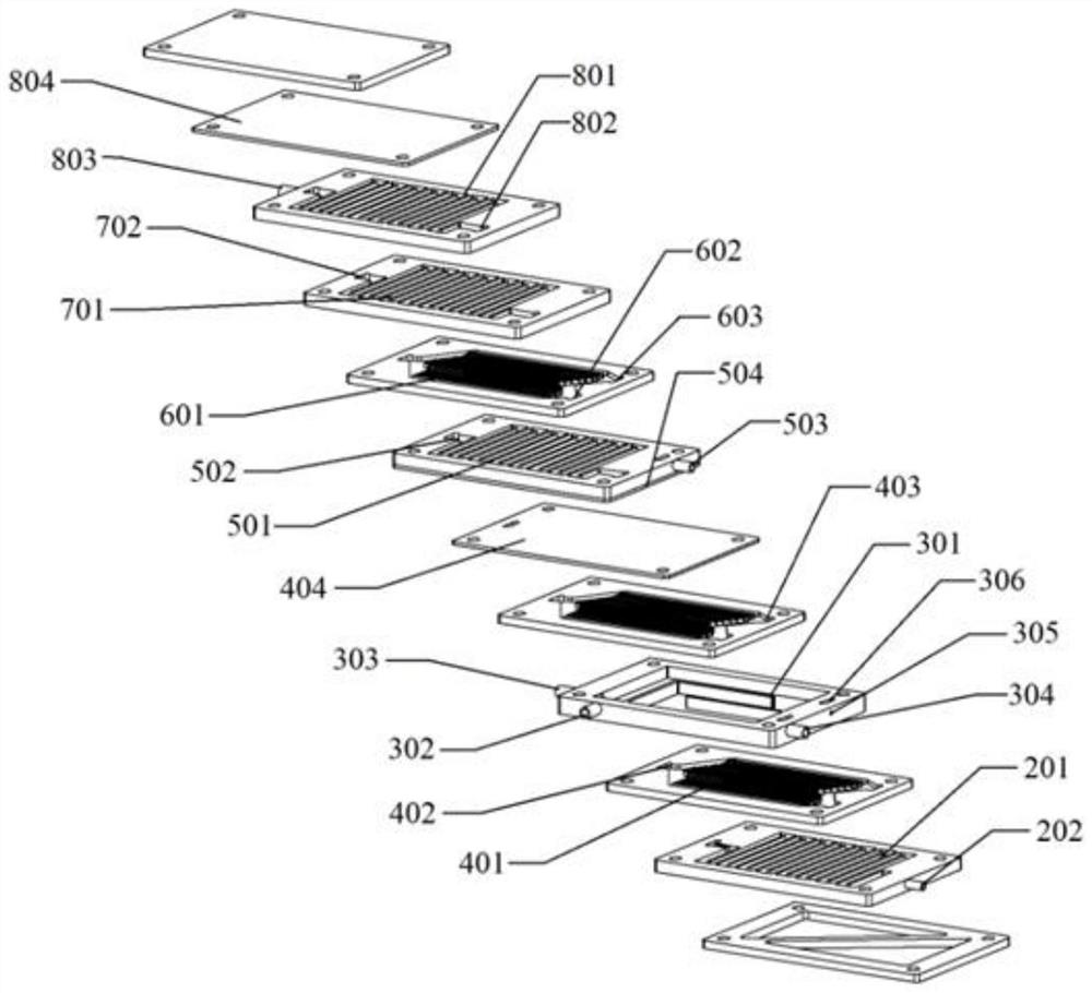
[0021] Specific implementation mode one: combine Figure 1 to Figure 8 Describe this embodiment mode, a kind of low-carbon monoxide micro-hydrogen generation device utilizing methanol steam reforming described in this embodiment mode includes lower end plate 1, gasification layer 2, combustion layer 3, two reforming layers 4, cooling layer 5, CO oxidation layer 6, drying layer 7, CO adsorption layer 8 and upper end plate 9, said lower end plate 1, gasification layer 2, two reforming layers 4, cooling layer 5, CO oxidation layer 6, drying layer 7, CO The adsorption layer 8 and the upper end plate 9 are sequentially stacked and connected from bottom to top, and the combustion layer 3 is arranged horizontally between the two reforming layers 4 .

specific Embodiment approach 2

[0022] Specific implementation mode two: combination Figure 1 to Figure 2 Describe this embodiment, the lower end plate 1, the gasification layer 2, the combustion layer 3, the two reforming layers 4, the cooling layer 5, the CO oxidation layer 6, the drying layer 7, the CO adsorption layer 8 and the upper end plate described in this embodiment Plates 9 are all rectangular plates with the same length and width. Other components and connections are the same as those in the first embodiment.

specific Embodiment approach 3

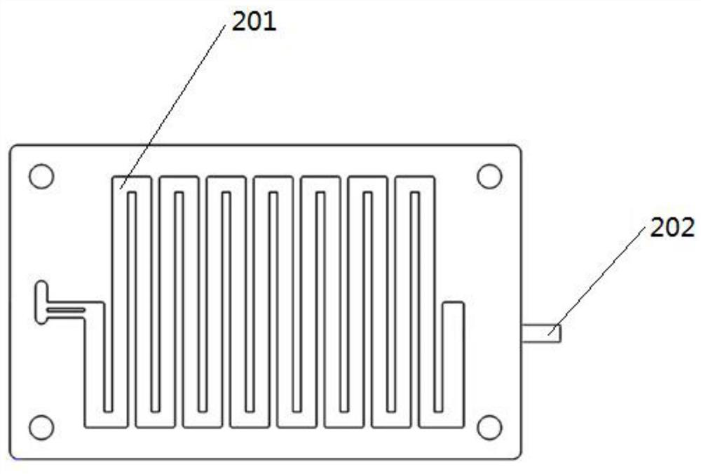
[0023] Specific implementation mode three: combination figure 2 and image 3 To describe this embodiment, the upper surface of the gasification layer 2 in this embodiment is provided with a gasification channel 201 , and one side wall of the gasification layer 2 is provided with a reforming raw material inlet hole 202 . The other components are the same as those in Embodiment 1 or 2 in terms of connections.

[0024] Specific implementation mode four: combination figure 2 and Figure 4 Describe this embodiment, the upper surface of combustion layer 3 described in this embodiment is provided with combustion cavity 301, and the outer wall of combustion layer 3 length direction is provided with fuel liquid inlet hole 302, and one side wall of combustion layer 3 width direction is provided with combustion-supporting chamber. The agent inlet 303, the other side wall of the combustion layer 3 in the width direction is provided with a combustion chamber fluid outlet 304 and a tem...


PUM


Abstract

A low-CO miniature hydrogen generating device using methanol steam reforming, which relates to a hydrogen generating device. The present invention solves the problem that the existing hydrogen generating device has poor hydrogen production effect and is not portable enough. The present invention includes a lower end plate , gasification layer, combustion layer, two reforming layers, cooling layer, CO oxidation layer, drying layer, CO adsorption layer and upper end plate, the lower end plate, gasification layer, two reforming layers, cooling layer, CO The oxidation layer, the desiccation layer, the CO adsorption layer and the upper end plate are stacked and connected sequentially from bottom to top, and the combustion layer is arranged horizontally between the two reforming layers. The invention belongs to the technical field of miniature hydrogen generation. The invention integrates the methanol steam reforming structure and the product gas CO treatment structure, has a compact structure and a smaller volume, and is suitable for portable applications.

Description

technical field [0001] The invention relates to a hydrogen generating device, in particular to a low-CO micro-hydrogen generating device utilizing methanol steam reforming, and belongs to the technical field of micro-hydrogen generation. Background technique [0002] CO, refers to the molecular formula of carbon monoxide, which is composed of an oxygen atom and a carbon atom connected by a covalent bond. Under normal conditions, carbon monoxide is a colorless, odorless, tasteless, poisonous gas with flammability, reduction and toxicity. . [0003] Fuel cell technology is an efficient and clean energy technology that converts chemical energy into electrical energy. Among them, low-temperature hydrogen-oxygen fuel cells with relatively mature technology have shown good application prospects due to their advantages such as simple structure, fast start-up, and low operating noise. But for portable applications, there are two problems with low-temperature oxyalkylene-based batt...

Claims


Application Information

Patent Timeline
Patent Type & Authority Patents(China)
IPC IPC(8): C01B3/32
CPCC01B3/323C01B2203/047C01B2203/1223
Inventor 曹伽牧陈俊宇张宇峰王玮琪李明雪刘晓为
Owner HARBIN INST OF TECH
Why Eureka
Try Eureka