Eureka AIR delivers breakthrough ideas for toughest innovation challenges, trusted by R&D personnel around the world.

Temporary power utilization system for construction site

A technology for temporary power consumption and construction sites, applied in information technology support systems, electrical components, circuit devices, etc., can solve problems such as difficult to effectively use qualified resources, difficult to achieve reliable power supply locking, and hidden dangers of major accidents

Pending Publication Date: 2020-06-16
中色十二冶金建设有限公司
View PDF6 Cites 4 Cited by
  • Summary
  • Abstract
  • Description
  • Claims
  • Application Information

AI Technical Summary

Problems solved by technology

[0002] Compared with the general power supply system, the power supply at the construction site has the characteristics of strong temporary, strong mobility, large scale changes, large phase changes, unfixed load, complex site conditions, relatively poor safety conditions, and relative electrical professional skills of power equipment operators. lower features
The management of the temporary power system on the construction site is different from the management of the general power supply system, and there are many security problems that are difficult to solve. For example, the wiring and dismantling, maintenance, and management of the temporary power system are facing huge difficulties.
[0003] Due to the relatively limited number of construction site electricians and temporary electrical technical management personnel with corresponding technical capabilities, they cannot meet the normal needs in terms of service time and frequency, while temporary electrical construction sites often have multiple points and wide areas, and the time span for wiring and dismantling, maintenance, and management is long. The workload of process response, maintenance and management is relatively large, which makes it difficult for the daily management of the power supply system to meet the safety and timeliness requirements of the power supply during the construction process. The actual situation in the process cannot quickly respond to the various needs of the power supply equipment during the construction process
Directly or indirectly, unsafe behaviors such as illegal use and change of electrical equipment, illegal wiring and dismantling, and troubleshooting without procedures and procedures are caused by the operators of electrical equipment, and there are great hidden dangers of accidents. It will lead to problems such as inadequate monitoring and maintenance of electrical equipment, frequent tripping of leakage protectors, etc.
[0004] In addition, the qualified resources that can be used in the construction process are difficult to effectively use, the data required for the relevant operation, management, and design modification required by the power supply are difficult to obtain reliably, the effective information is difficult to be quickly transmitted and effectively utilized, and the risk factors of electricity use are difficult to be discovered and resolved in time. Timely processing, it is difficult to reliably lock the power supply in the maintenance process of the power supply system and the equipment used for the power supply, and the phenomenon of wrong power supply may also occur. The misoperation and refusal of the protection equipment of the power supply system cannot be discovered and analyzed in time and eliminated in time. It is difficult to monitor and adjust in time if there is an overall or partial imbalance with the reactive power load

Method used


Image

  • Temporary power utilization system for construction site
  • Temporary power utilization system for construction site
  • Temporary power utilization system for construction site

Examples


Embodiment Construction

[0036] In order to further explain the technical means and effects that the present invention takes to achieve the intended purpose of the invention, below in conjunction with the accompanying drawings and preferred embodiments, the specific implementation, structure, features and details of the construction site temporary power system proposed according to the present invention will be described below. Its effect is described in detail below.

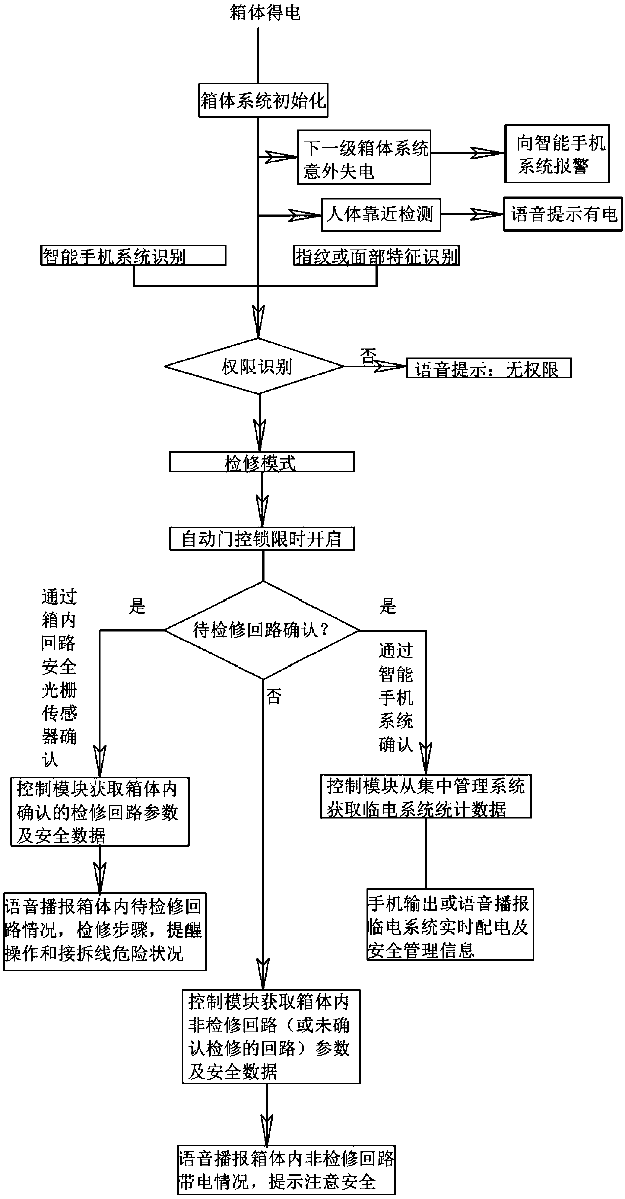
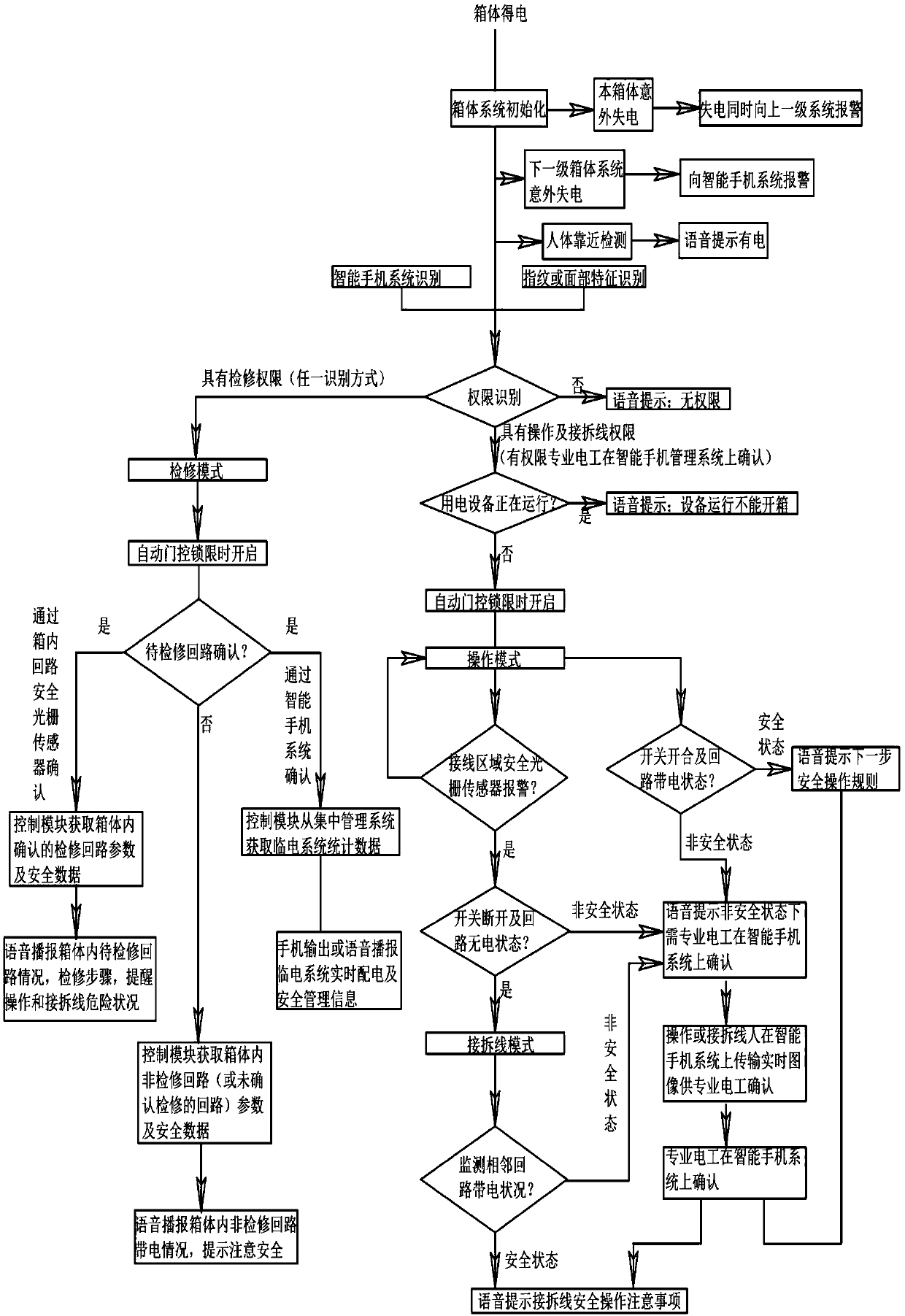
[0037] figure 1 It is a schematic illustration of an embodiment of the construction site temporary power consumption system 100 of the present invention. see figure 1 , the construction site temporary electricity system 100 of the example of the present invention mainly includes: an on-site intelligent equipment layer, an intelligent management layer and a network communication layer; the on-site intelligent equipment layer includes one or more box intelligent subsystems (not shown in the figure) ; The intelligent management layer in...


PUM


Abstract

The invention relates to a temporary power utilization system for a construction site. The system comprises one or more box body intelligent subsystems, a remote management subsystem and a centralizedintelligent management subsystem; the box body intelligent subsystems are used for the intelligent management of box bodies, wherein the box bodies are general distribution boxes, branch distributionboxes or switch boxes; the remote management subsystem is used for remotely managing the box body intelligent subsystems; the centralized intelligent management subsystem is used for acquiring the information of the box body intelligent subsystems and the remote management subsystem and processing, sorting, storing, analyzing and outputting the information; the box body intelligent subsystems andthe centralized intelligent management subsystem are in electric connection and communication connection through low-voltage distribution lines and carrier communication units; and the remote management subsystem and the centralized intelligent management subsystem are in communication connection through a wireless network unit. By means of the temporary power utilization system for the construction site, the safety of the temporary power utilization of the construction site can be improved, management, process maintenance and timely monitoring are facilitated, and process efficiency can be improved.

Description

technical field [0001] The invention relates to the field of power utilization, in particular to a temporary power utilization system at a construction site. Background technique [0002] Compared with the general power supply system, the power supply at the construction site has the characteristics of strong temporary, strong mobility, large scale changes, large phase changes, unfixed load, complex site conditions, relatively poor safety conditions, and relative electrical professional skills of power equipment operators. lower features. The management of the temporary power system on the construction site is different from the management of the general power supply system, and there are many safety problems that are difficult to solve. For example, the wiring and dismantling, maintenance, and management of the temporary power system are facing huge difficulties. [0003] Due to the relatively limited number of construction site electricians and temporary electrical techni...

Claims


Application Information

Patent Timeline
IPC IPC(8): H02J13/00
CPCY02E60/00Y04S40/126Y02B90/20
Inventor 岳雪钢魏树光王永奎庞文佳孙媛月
Owner 中色十二冶金建设有限公司
Why Eureka
Eureka Blog
Learn More